
USER MANUAL
WiFiber 1200R
Version of this manual: 1.31
GPON/EPON Wireless AC 1200 Mbps Optical Modem.
Congratulations, you have just purchased a product with Intelbras quality and safety.
The WiFiber 1200R has 1 PON uplink port serving at speeds: 2.5/1.25 Gbps Downstream/Upstream, as well as 2 Gigabit Ethernet ports and 2 wireless interfaces, one in the IEEE b/g/n standard and the other a/n/ac. The Intelbras WiFiber 1200R is designed for advanced implementations and provides a low cost and high performance alternative for GPON/EPON solution with 5.0Ghz wifi. Its installation and management can be done through the web interface, quickly and easily.
 ATTENTION: this product comes with a factory default password. For your safety, it is ESSENTIAL that you change it as soon as you install the product.

This equipment does not have the right to be protected against harmful interference and cannot cause interference to properly authorized systems.

This product is homologated by Anatel, the homologation number is on the product label, for inquiries use the link sistemas.anatel.gov.br/sch.
2. EXPORT TO PDF
To export this manual to PDF file format, click on the icon in the upper right corner of your screen, or use the print feature that browsers such as Google Chrome.® and Mozilla Firefox® have. To access it, press the CTRL + P keys or click here. If you prefer, use the browser menu, accessing the Print tab, which is usually located in the upper right corner of the screen. On the screen that will open, follow the steps below, according to the browser:
Google Chrome®: in the print screen, in the Destination field,, click Change, select the Save as PDF option in the Local Destinations section and click Save. The operating system screen will open asking you to define the name and where to save the file.
Mozilla Firefox®: in the print screen, click Print, in the General tab, select the Print to file option, in the file field, define the name and location where the file should be saved, select PDF as the output format and click Print.
3. CAUTION AND SECURITY
This section presents the standards adopted in the web manager and in this manual.
Data protection and security
» Abide by local laws concerning the protection and use of such data and the regulations that prevail in the country.
» The purpose of data protection legislation is to prevent infringements on individual privacy rights based on the misuse of personal data. » LGPD - General Law of Personal Data Protection: this product processes personal data, however, Intelbras does not have access to the data originated from this product. This product has encrypted personal data storage.Guidelines that apply to Intelbras employees
» Intelbras employees are subject to secure commerce practices and data confidentiality under the terms of the company's work procedures.
» It is imperative that the following rules are observed to ensure that the statutory provisions regarding services (whether in-house services or remote administration and maintenance) are strictly followed. This preserves the client's interests and provides additional personal protection.Guidelines that control data processing
» Ensure that only authorized persons have access to customer data.
» Use password assignment facilities, without allowing any exceptions. Never give out passwords to unauthorized people.» Ensure that no unauthorized person has the means to process (store, modify, transmit, disable, or delete) or use customer data.» Prevent unauthorized persons from gaining access to data media, for example, backup disks or protocol printouts.» Ensure that data media that are no longer needed are completely destroyed and that documents are not stored or left in generally accessible locations.» Working together with the client builds trust.User misuse and hacking
» The access passwords to the product information allow the attainment and alteration of any facility, such as external access to the company's system to obtain data and make calls, therefore, it is of utmost importance that the passwords are made available only to those who are authorized to use them, under the risk of misuse.
» The product has security settings that can be enabled, and that will be addressed in this manual, however, it is essential that the user ensures the security of the network on which the product is installed, since the manufacturer is not responsible for the invasion of the product through hacker and cracker attacks.Laser safety warning
The Intelbras WiFiber 1200R has a laser emitting source that emits light energy in optical fiber cables. This energy is within the infrared (invisible) region of the red (visible) electromagnetic spectrum.
Certain procedures performed during testing require the manipulation of optical fibers without the use of protective caps, thus increasing the risk of exposure. Exposure to any visible or invisible laser may damage your eyes under certain conditions.Caution: Avoid direct exposure to the ends of optical connectors. Laser radiation may be present and could damage your eyes. Never look directly into an active fiber optic or fiber optic connector of a device that is powered.4. TECHNICAL SPECIFICATIONS
| Specifications | Values |
|---|---|
| Dimensions(L x A x P) | (237,5 x 158,6 x 40) mm |
| Operation Environment | Operation temperature 0°C ~ 50°C Relative Humidity: 10% ~ 90% (Without condensation) | Storage Environment | Storage temperature: 0 ºC ~ 70 ºCRelative humidity: 10% ~ 90% (Without condensation) |
| Power supply (externa) | Input: 100–240Vca ~ 50/60 HzOutput: 12Vdc ~ 1A |
| Maximum Consumption Power | 12W |
| Ethernet/PON Chipset | RTL9607C |
| Wireless Chipset | RTL8812FR-CG & RTL8192FR-CG |
| Flash Memory | 128 Mb | SDRAM Memory | 128 Mb | Optical interface | 1 SC/APC port |
| TX wavelength: 1310 nm | |
| RX wavelength: 1490 nm | |
| Maximum receiver sensitivity - 8 dBm | |
| Minimum receiver sensitivity -28 dBm | |
| GPON | Minimum receiver sensitivity -28 dBm |
| 1.25 Gbps upstream (transmitter) | |
| 2.5 Gbps downstream (receiver) | |
| Class B+ optical system | |
| EPON | Compliant with IEEE.802.3ah.EPON |
| 1.25 Gbps upstream (transmitter) | |
| 2.5 Gbps downstream (receiver) | Ethernet Interface | 2 Gigabit Ethernet ports(10/100/1000BASE-T Ethernet) |
| 2 RJ45 connectors | |
| Compliant with IEEE 802.3 specifications | |
| Auto MDI/MDIX | |
| autonegotiation | |
| Configuration types | Bridge mode |
| Router mode | |
| PPPoE mode | |
| Supported standards | Compatible with ITU-T G.984 |
| Compatible with IEEE 802.3ah EPON | |
| Compatible with IEEE 802.3 Ethernet | |
| Compatible with IEEE 802.1q/p VLANs | |
| Compatible with IEEE 802.3u Fast Ethernet | |
| Compatible with IEEE 802.3ab 1000BASE-T | |
| Supported GPON and Ethernet/IP Protocols | GPON » ITU-T G.984 (GPON)» 32 T-CONTS per device» 128 GEM Ports per device» Flexible mapping between GEM Ports and T-CONTS with priority queue-based scheduling» Activation with automatic discovery of SN and password in compliance with ITU-TG.984.3» AES-128 decoding with key generation and switching» FEC (Forward Error Correction)» Multicast GEM Port Support |
| Ethernet/IP» Bridging and switching (802.1D / 802.1Q)» Four traffic classes with 802.1p» 802.3x Flow control» VLAN tagging/untagging | IPTV | IGMP multicast | Call Transfer. | OMCI (compliant with G.984.4) |
| Web UI | |
| TR-069 | |
| CPE-MGR | |
| Wireless Standard | IEEE 802.11a/b/g/n/ac |
| Radio mode | MU-MIMO |
| Antennas | 2 fixed 5dBi antennas |
| Operation frequencies | 2.4Ghz/5.0Ghz |
| Bandwidth | 2.4Ghz: 20, 40MHz |
| 5.0Ghz: 20, 40, 80Mhz | |
| Transmission rate | 2.4Ghz: Até 300Mbps |
| 5.0Ghz: Até 867Mbps | |
| Operation channels 2.4Ghz: | 1-13 |
| Operation channels 5.0Ghz: | 36, 40, 44, 48, 149, 153, 157, 161 |
| 52, 56, 60, 64, 100, 104, 108, 112 (DFS)
|
|
| Maximum power (E.I.R.P.) | 2.4Ghz: 25dBm |
| 5.0Ghz:24dBm | |
| 2.4Ghz receiver sensitivity | 802.11b 11Mbps: -88dBm |
| 802.11g 54Mbps: -75dBm | |
| 802.11n 20Mhz MCS7: -72dBm | |
| 802.11n 40Mhz MCS7: -70dBm | |
| 5.0Ghz receiver sensitivity | |
| 802.11a 54Mbps: -75dBm | |
| 802.11n 40Mhz MCS7: -70dBm | |
| 802.11ac 80Mhz MCS9: -60dBm | |
| Maximum capacity of simultaneous clients | 64 |
| Security | WEP/WPA2/WPA2 MIXED |
5. ACCESSORIES
» Power Supply.
6. MANAGEMENT
In this manual we will address the configuration performed via computer locally. However, if you wish, you can perform the process using the remote management available after activating and configuring the CPE-MGR function available in the Intelbras OLT.
6.1. Remote access (web)
The WiFiber 1200R can be remotely managed through the web interface (HTTP) after its inclusion in the CPE-MGR function available in the Intelbras OLT. Remote access uses VLAN 7 as the default remote management VLAN, allowing an IP address to be automatically assigned when connected to the Intelbras OLT.
6.2. Local access (web)
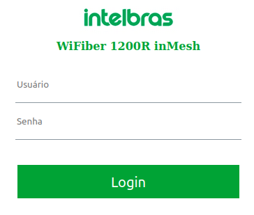
The WiFiber 1200R can be managed locally via the web interface (HTTP). This document will use the web interface for example settings.To access the web interface, once connected to your optical modem network via cable or Wi-Fi, open your web browser and type http://192.168.1.1 in the address field, you will be prompted for the user name and password to authenticate to the system, fill it in:
| Username | admin |
| Password | intelbras |
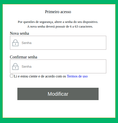
6.3. First Access (web)
When the user first logs in with the default password on the WiFiber 1200R, he will be asked to change the default password (for security reasons) and to read and accept the terms of use available in the product through the hyperlink in blue.
7. CONFIGURATION
After authenticating to the system the WiFiber 1200R configuration interface will be displayed.
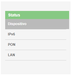
7.1. Product information
The Status menu provides information about the optical modem's settings, including the LAN, WAN, PON, and VoIP interfaces, as well as system-related information such as firmware version, CPU usage, and memory. You can navigate between the submenus to check each type of information available.
7.2. LAN Interface
Through this menu you can make settings for the LAN interface.
7.3. LAN Settings
This page is used to configure the optical Modem's LAN interface.
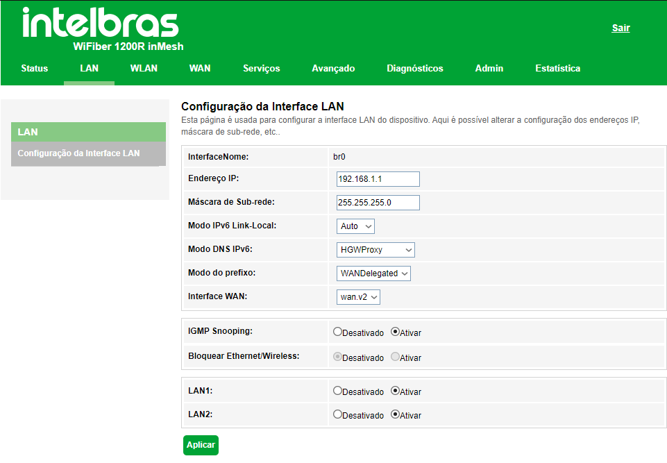
» IP address: enter the IP address used on the LAN interface.
» Subnet Mask: enter the netmask used by the LAN IP address.
» IPv6 Link-Local mode: select the LAN interface IPv6 configuration mode: Auto or Static: Auto or Static
- Auto: In this mode the local link interface will be automatically configured.
- Static: in this mode the user is allowed to assign an IPv6 address on the LAN interface.
» IPv6DNS mode: Client connected on the LAN receives as DNS address the IPv6 Local Link of the ONT LAN.
- HGWProxy: Responsible for changing the way the DNS server is acquired.
- WANConnection: The ONT passes the DNS received by the WAN on to the LAN.
- Static: You choose the DNS server manually.
» Perfix mode: Defines how the IPv6 prefix will be given, for most scenarios the /64 prefix is used.
- WANDelegated: ONT passes the prefix from WAN to LAN.
- Static: You choose the IPv6 network prefix.
» Interface WAN: Select the desired IPv6 WAN interface.
» IGMP Snooping: if enabled, the optical modem will analyze IGMP messages received from devices connected totheLAN port, allowing them to join the multicast group (normally used in IPTV).
»Lan 1 and Lan 2: here you can set whether or not the Wifiber lan ports are available for traffic.
- Enable: the lan port works normally.
- Disable: the port is deactivated and no more traffic flows through it.
7.4. Wireless Interface
Through the WLAN menu you can configure the inMesh and the 2.4GHz and 5GHz wireless interfaces.
7.4.1. Interface Settings
This page is used for configuration of the 2.4GHz and 5GHz wireless interfaces.
7.4.2. Basic Settings
On this page you can configure some basic parameters for connecting wireless clients.
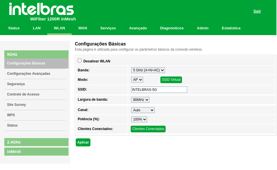
» Disable WLAN: if disabled, wireless clients will not be able to connect to the optical modem.
» Band: select the wireless network communication standard.
» Mode: Only AP(Access Point) mode is available. In this mode wireless clients can connect to this equipment.
» virtual SSID: in this option you can enable up to 4 virtual SSIDs.
» SSID: enter the wireless network name.
The characters that are accepted by the SSID field are:
• Capital letters: A to Z (26 characters).
• Lower case letters: a to z (26 characters).
• Numbers: 0 to 9 (10 characters).
• Symbols: (space) ! “ # $ % & ‘ ( ) * + , - . / : ; < = > ? @ [ \ ] ^ _` { | } ~ (33 characters).
Any other characters are not accepted.
» Bandwidth: Select the bandwidth. The 802.11 a/n/ac standard allows you to select three different bandwidths: 20MHz, 40MHz and 80MHz.
» Channel: select the desired channel or use the Auto option, which will try to find an unused or less busy channel.
» Power (%): select the radio transmission power.
» Connected clients: displays a list of wireless clients on the 5GHz interface that are currently associated.
7.4.3. Advanced settings
This page can be used by advanced users with wireless networking knowledge. We recommend that you do not change this information as performance degradation caused by improper settings can occur.
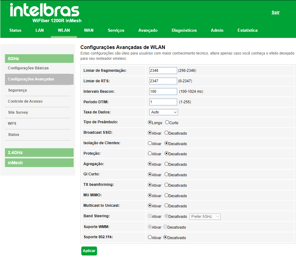
» Fragmentation threshold: Enter the packet fragmentation threshold. Packets above this value will befragmented. Setting a value that is too low can result in poor network performance. The default value2346 is thebest option in most cases.
» RTS threshold: enter the threshold for activating flow control to help with the data collision problem. Packets abovethis value will activate flow control.
» Beacon Interval: defines the time interval between a beacon frame transmission.
» DTIM Period: is the time period between when DTIMs are sent to network clients. Enter the time in second(s).
» Data Rate: select the maximum data transmission rate (in Mbps). The equipment will always try to transmit atmaximum speed, when possible. If necessary, the data rate will be reduced automatically (in-terference, packet loss).Default value Auto.
» Preamble type: select the wait and sync time that precedes the transmission of each frame, the long one being 128bits and the short one 56 bits.
» Broadcast SSID: if enabled, the SSID will be broadcast in the network.
» Client Isolation: if enabled, prevents a client from having connectivity to another via Wireless interface, even if connected to the same SSID.
» Aggregation: enabled by default. This is a part of the 802.11 n standard, allowing multiple frames to be sent by singleaccess to the medium, combining frames into a larger frame.
» Short GI: disabled by default. If enabled, enables the short guard interval.
» TX beamforming: if enabled, allows you to focus a signal in a specific direction, which reflects in a higher quality ofsignal to the receiver.
» Multicast to Unicast: if enabled, converts multicast packets to unicastin order to decrease packet loss, especiallyin scenarios where streaming media exists.
» Band Steering: defines which band is the main band for devices to connect to.
» WMM support: allows traffic prioritization according to the offered service.
» 802.11k support: if enabled, allows you to create an optimized channel list to help devices speed up the search fornearby APs that are available as roaming destinations.
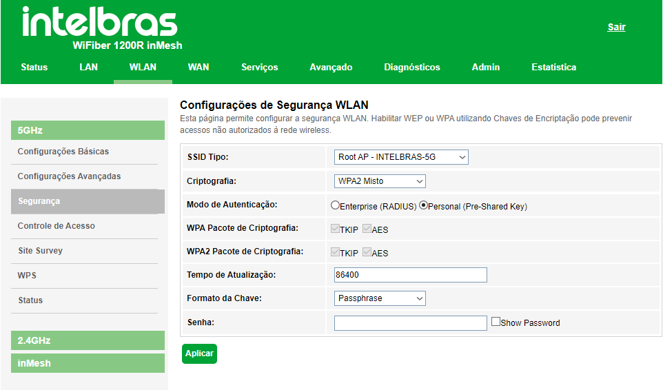
7.4.4. Security
On this page you can configure the security options. Enable at least one security method to prevent unauthorized access to the wireless network.
WEP security method options
» WEP: it is based on the 802.11 standard and uses the RC4 encryption algorithm. This is an old encryptionalgorithm and can be decrypted in less than 10 minutes. We recommend using WPA2 or WPA2 Mixed methods.
» 802.1x authentication: if enabled, enables RADIUS-based authentication using WEP64 or WEP128 keys.Requires RADIUS server.
» RADIUS Information: enter the RADIUS server information.
» Authentication: select the authentication method:
• Open system: open system authentication with WEP64 or WEP128 key.
• Shared key: shared key authentication with WEP64 or WEP128 key.
• Auto: automatic authentication with WEP64 or WEP128 key.
» Key Length: select the size of the key.
• 64 bit: defines the number of characters of the key, 5 ASCII ou 10 Hexa.
• 128 bit: defines the number of characters of the key, 10 ASCII ou 26 Hexa.
» Encryption key: enter the desired security key.
WPA2 security method options
» WPA2: this method is safe and required for use on 802.11n.
» Authentication mode: select the authentication method:
• Enterprise (RADIUS): if enabled, allows RADIUS-based authentication.
· IP address of the RADIUS server: enter the IP address where the RADIUS server is located.
· Port of the RADIUS server: insert the port configured for RADIUS server operation.
· Password for the RADIUS server: enter the password configured for the RADIUS server.
• Personal (Pre-Shared Key): if enabled, allows you to use a predefined key for encryption during datatransmission.
» Update Time: time for key exchange.
» Key format: select the predefined key format:
• Passphrase: allows the use of keys with 8 to 63 ASCII characters.
• HEXA: allows the use of a 64-character hexadecimal key.
» Password: enter the desired security key.
WPA2 mixed security method options
» Mixed WPA2: this method mixes WPA and WPA2.
» Authentication mode: select the authentication method:
• Enterprise (RADIUS): if enabled, enables RADIUS-based authentication.
· IP address of the RADIUS server: enter the IP address where the RADIUS server is located.
· RADIUS server port: enter the port configured for RADIUS server operation.
· RADIUS server password: enter the password configured for the RADIUS server.
• Personal (Pre-Shared Key): if enabled, allows you to use a predefined key for encryption during datatransmission.
» Update time: time for key exchange.
» Key format: select the predefined key format:
• Passphrase: allows the use of keys with 8 to 63 ASCII characters.
• HEXA: allows the use of a 64-character hexadecimal key.
» Password: enter the desired security key.
WPA3 security method options
» WPA3: It is the most up-to-date and safe method, offering more security for data exchange within the network byadding a number of protection features, such as a new type of encryption and resistance to "brute force" attacks
» Update time: time for key exchange.
» Password: enter the desired security key.
WPA2+WPA3 Mixed Security Method Options
» WPA2+WPA3 Mixed: it is a transition method, where older devices that do not support WPA3 encryption technologyare allowed to use WPA2.
7.4.5. Access Control
On this page you can configure a wireless network access control list, based on the MAC address of the wireless client.
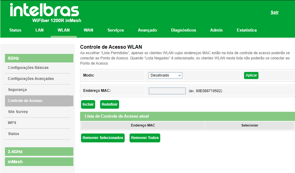
» Mode: select the operation mode from the list:
• Disabled: Disables the access control function.
• Allowed list: allows only MAC addresses registered on the list to access the wireless network.
• Denied List: does not allow MAC addresses that are registered on the list to access the wireless network.
» MAC address: Enter the desired MAC address. Use the format (e.g.: 00E086710502).
» Current access control list: displays the list of configured MAC addresses.
7.4.6. Site Survey
Tool to scan neaighbor wireless networks.
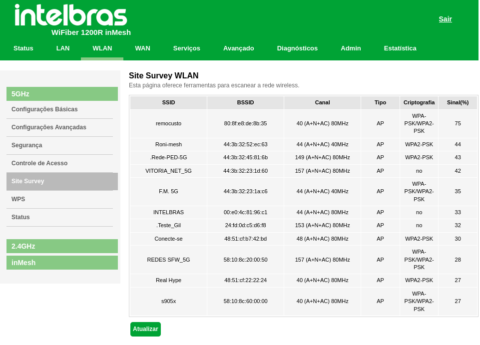
» Botão Update:Updates the list of neighbor wireless networks.
7.4.7. WPS
WPSThrough this process, you can add clients to the wireless network without the need for any specific configuration, such as SSID, security mode or password. WPS (Wi-Fi Protected Setup) is an easy way to connect to an optical wireless modem. To add a wireless client to the optical modem, the client must support WPS.
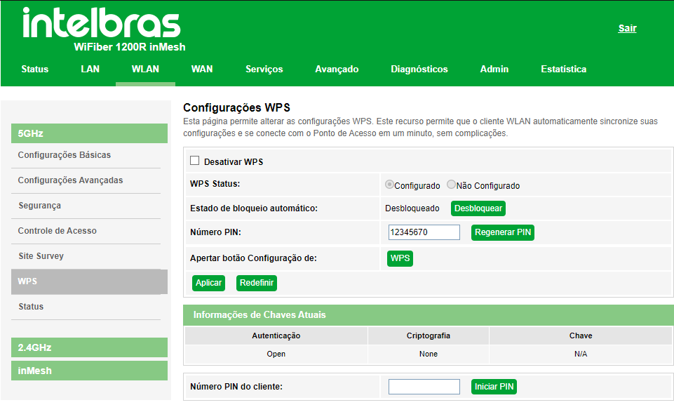
» Disable WPS: If enabled, the optical modem's WPS function will be disabled
» WPS status: displays the current status of the WPS function (Configured or Not Configured).
» PIN Number: when pressing the button, a new PIN number will be generated.
» WPS Button: By pressing the button the optical modem will start the Push Button style WPS configurationprocedure. The optical modem will wait for WPS requests from wireless clients for about two minutes.
» Client PIN number: number:enter the PIN code specified by the wireless client you wish to connect to and click on the Start PIN button.
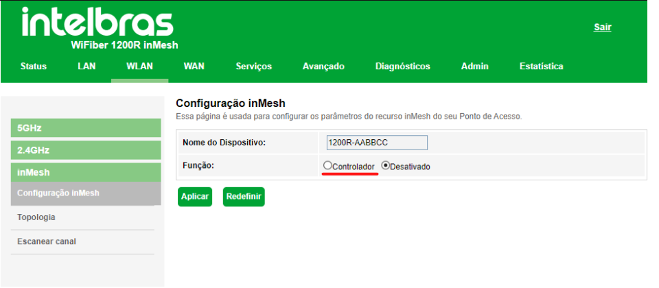
7.4.8. inMesh
inMesh configuration
 ATTENTION: before you start, make sure your products are up to date with the latest version available on the site (it has Mesh support).
If you are using Band Steering, configure the 5 GHz and 2.4 GHz network with the same SSID and password, WPA2 encryption, and set a static channel on the 5GHz frequency
After setting up the Wi-Fi network, click WLAN > inMesh, check the controller function and apply the configuration.
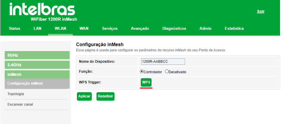
To add another router to your ONT's mesh network, it must be from the Wi-Force line and be updated to the latest available firmware version.
With the router at the factory default, turn it on next to your ONT. On the Wifiber, click on the WPS button on the web interface, notice that its 5G and 2.4G leds will start blinking, when it stops blinking it means that the pairing between the ONT and the router has been completed.
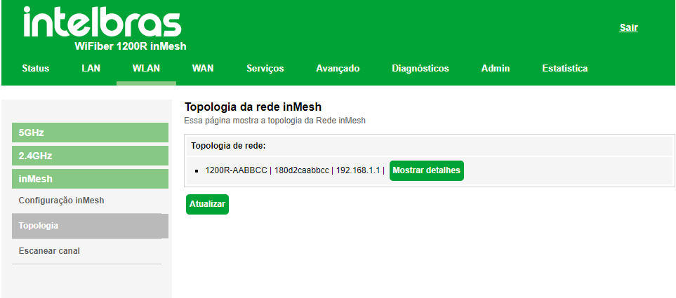
Topology
Here you can see the routers connected to your network.
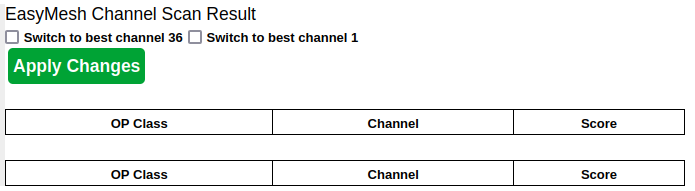
Scan Channel
In this topic, you can scan the network to find the best channel to use.
7.5. WAN Interface
Using the WAN menu you can make WAN interface settings for both IPv4 and IPv6 connections.
7.5.1. WAN Settings
This page is used to configure the WAN interface and also to link the LAN interfaces that will have access to the services.
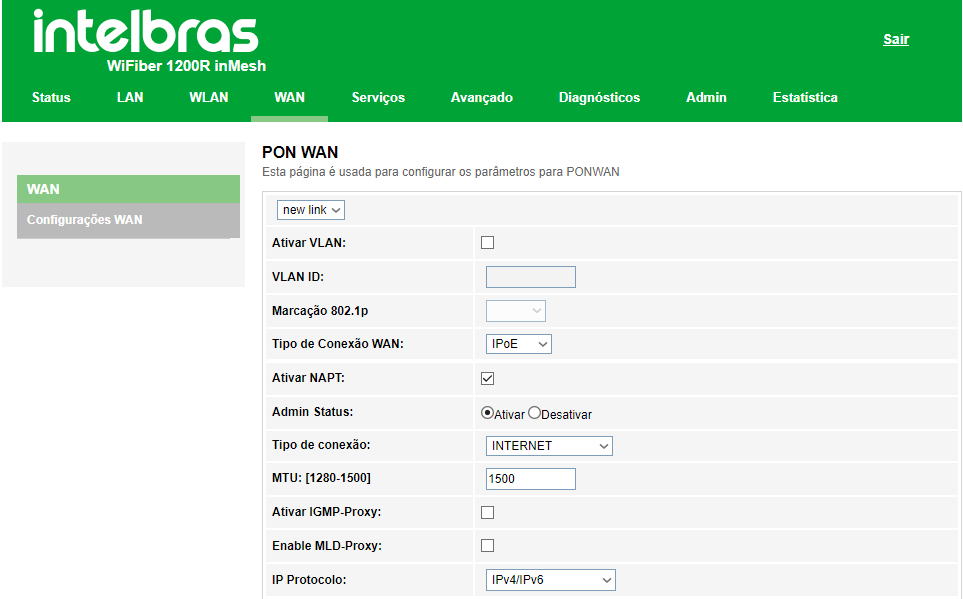
» WAN interface selection: para criar nova interface WAN, selecione new Link. Para modificar uma interface WAN selecione a interface desejada.
» Activate VLAN: selecione esta opção para configurar a VLAN utiizada pela interface WAN.
» 802.1p Marking: selecione a marcação 802.1p que o modem óptico colocará no pacote quando o pacote for transmitido para o uplink. Caso não for selecionado nenhum valor, o modem óptico colocará 0 (valor-padrão).
» Vlan de Multicast:_____________________________
» WAN connection type: select the operating mode for the WAN interface. For each operating mode, the possiblesettings will be displayed:
• Bridge: In this mode, the WAN interface will be bridged with the selected LAN port. The NAT and IGMP Proxyfunctions will be disabled.
• IPoE: In this mode the WAN interface can be configured as a DHCP client or Static IP.
• PPPoE: In this mode, the WAN interface will be configured as a PPPoE client.
» Activate NAPT: enables the WAN interface when performing NAT. The optical modem will enable, by default, whenIPoE and PPPoE options are selected. Intelbras recommends that you do not change this option.
» Admin Status: enables or disables the WAN interface.
» Connection type: select which type of service will be linked to the configured WAN interface:
• Other: normally used to link the video service (IPTV).
• TR069: the WAN interface will be linked to the TR-069 service
• INTERNET: the WAN interface will be linked to the Internet service
• INTERNET_TR069: the WAN interface will be linked to the Internet service and TR-069
• VOICE: the WAN interface will be linked to the voice service.
• VOICE_TR069: the WAN interface will be tied to the voice service and TR-069
• VOICE_INTERNET: the WAN interface will be linked to the voice and Internet service
• VOICE_INTERNET_TR069: the WAN interface will be linked to the voice, internet, and TR-069 service.
» MTU: maximum packet transmission size. Change the default value set by the optical modem only if requested byyour service provider.
» Enable IGMP-Proxy: if enabled, the optical modem will forward upstream the IGMP messages received by thecomputers connected on the LAN interface.
» Enable MLD-Proxy: if enabled, the selected WAN interface will act as an MLD proxy.
» IP Protocol: select the desired protocol:
• IPv4: in this mode, the WAN interface will only allow IPv4 configuration.
• IPv6: in this mode, the WAN interface will only allow IPv6 configuration.
• IPv4/IPv6: in this mode, the WAN interface will allow both IPv4 and IPv6 configuration.
IPoE Client mode settings
Information regarding the IPoE mode configuration (Static or Dynamic IP)
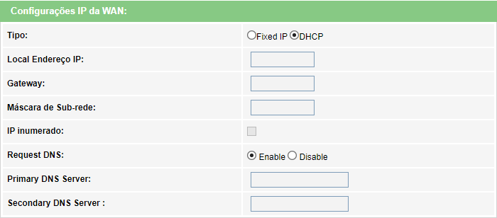
» Type: select the operating mode for the WAN interface:
ta• Fixed IP: In this mode, you will need to manually enter all the WAN connection information.
• DHCP: In this mode the WAN interface will be configured automatically, according to information sent by yourInternet provider.
» Local IP Address: only available in Fixed IP mode. Enter the IP address of the WAN interface, as reported by yourInternet provider..
» Gateway: available only in Fixed IP mode. Enter the netmask used by the WAN interface, as reported by yourInternet provider.
» Subnet Mask: available only in Fixed IP mode. Enter the netmask used by the WAN interface, as reported by yourInternet provider.
» Request DNS: if enabled, the DNS address used by the WAN interface will be assigned automatically by yourInternet provider. Only available for DHCP mode
» Primary DNS server: only available if Request DNS is disabled. Manually enter the address of the primary DNSserver.
» Secondary DNS server: only available if Request DNS is disabled. Manually enter the address of the secondaryDNS server.
PPPoE Client mode settings
Information regarding the configuration of the PPPoE Client mode.
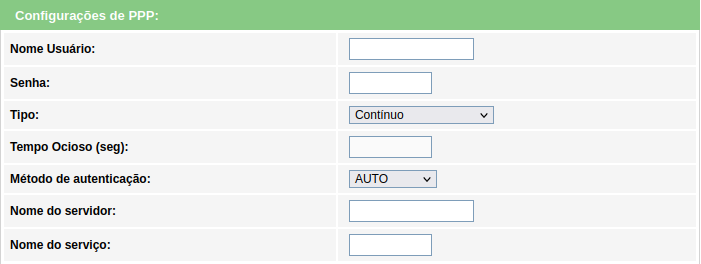
» User Name: enter the user name used for PPPoE authentication.
» Password: enter the password of the user used for PPPoE authentication.
» Type: select the connection method:
• Continuous: default option, change only if requested by your Internet Service Provider.
• Connect on demand: select this method only if required by your internet service provider.
• Manual: select this method only if required by your internet service provider.
» Idle Time (seg): only configure this field if required by your internet service provider..
» Authentication method: select the authentication method:
• Auto: opção padrão, altere este campo apenas se solicitado por seu provedor de internet.
• PAP: select this method only if required by your internet service provider.
• CHAP: select this method only if required by your internet service provider.
• MSCHAP: select this method only if required by your internet service provider.
• MSCHAPV2: select this method only if required by your internet service provider.
» Server Name: optional field, to be filled in only if requested by your internet service provider.
» Server Name: optional field, to be filled in only if requested by your internet service provider.
Configuration of IPv6 addressing mode
When you select the IPv6 option during WAN interface configuration, the following configuration information will be available.
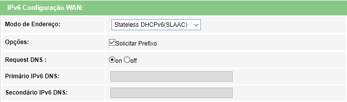
» Address mode: selecione o método de atribuição do endereço IPv6 na interface WAN:
• Stateless DHCPv6(SLAAC): if selected, the WAN interface will autoconfigure the global IPv6 address from theprefix received from the RA(Router Advertisement) message.
• Static: if selected, you will be prompted to configure the IPv6 addresses manually.
» Request DNS: if enabled, the DNS address used by the WAN interface will be assigned automatically by yourInternet Service Provider. Only available for DHCPv6 mode.
» Primary IPv6 DNS: available only for static mode. Enter the IPv6 address of the primary DNS server, as reportedby your Internet Service Provider.
» Secondary IPv6 DNS: available only for static mode. Enter the IPv6 address of the secondary DNS server, asreported by your Internet Service Provider.
Port mapping
This option is used to link one or more LAN ports with the desired WAN interface. Select the interfaces as needed.

Note.: » You cannot select the same LAN port for different WAN interfaces, in which case the last setting made will be the valid one.
» Se uma determinada porta não for selecionada por nenhuma interface WAN, significa que ela terá comunicação com todas as interfaces WAN configuradas e utilizará a interface.
» We recommend using up to 4 different DNS servers.
7.6. Services
Through this menu you can configure the services made available by the optical modem.
7.6.1.1 DHCP Settings
This page is used to configure how the optical modem will act as a DHCP server.
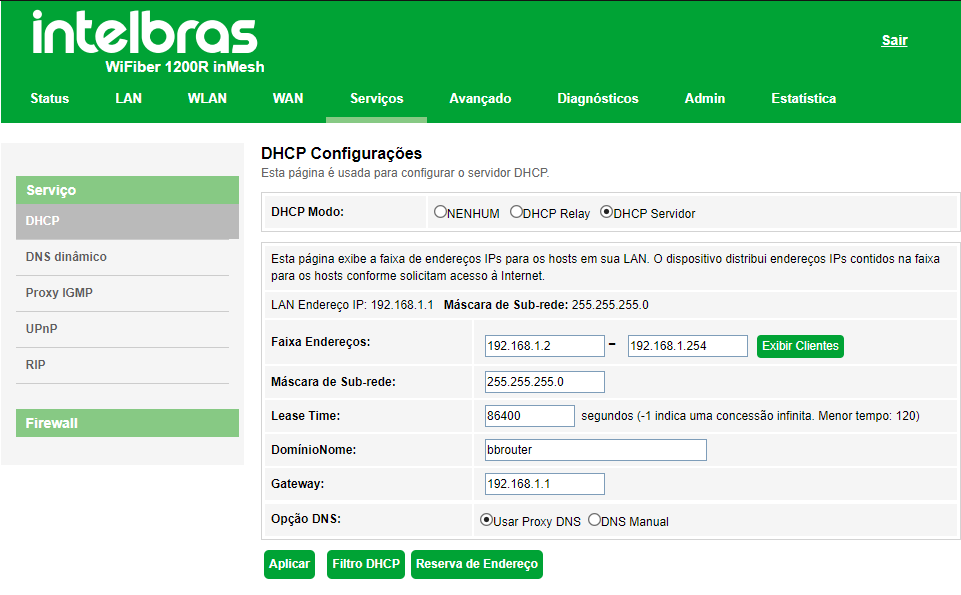
» DHCP mode: select the desired option: None, DHCP Relay or DHCP Server.
• None: desativa o modo DHCP.
• DHCP Relay: enter the IP address of the DHCP server to which the optical modem will forward messages.
• DHCP Server: the optical modem will act as a DHCP server. The equipment connected to the LAN port thatrequests information from the optical modem will receive the configured information.
• DHCP Client: the optical modem will behave as a DHCP client. The devices connected to the LAN port thatrequest information from the optical modem will receive the configured information.
» DHCP Server mode:
• Address ranges: enter the start and end IP address distributed by the DHCP server.
• Subnet mask: enter the network mask used by the DHCP server.• Lease Time: time in seconds that the IP address assigned to the client will be valid.
• Domain: name of the domain assigned to the IP address.
• Gateway: enter the IP address of the gateway that will be assigned to the client.
• DNS Option: use DNS Relay or Manual DNS:
· DNS Relay: In this mode, the optical modem will tell the client it is the DNS server and then make therequested DNS requests.
· Manual DNS: In this mode the DNS server addresses must be entered manually.
» DHCP filter: this option is used to configure the filter based on the port.
» Address reservation: this option is used to configure static IP based on MAC address.
» Display clients: clients:displays a list with the IP address, MAC address, and expiration time of each assigned DHCPclient.
7.6.1.2. Dynamic DNS configuration
On this page you can add dynamic hosts from No-IP®, DynDNS® and TZO® services directly to your optical modem. You must register your information directly on the website of one of the services, and then inform the optical modem of the parameters for authentication.
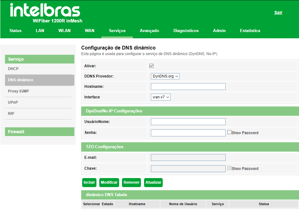
» Enable: Select the option for configuring the DDNS server credentials.
» DDNS Provider: select the desired DDNS server: DynDNS®, No-IP® or TZO®.
» Hostname: enter the host name as registered with your DDNS provider.
» Interface: select the WAN interface used to establish communication with the DDNS server.
DynDNS® and No-IP® Configurations
» User: enter the username as registered with your DDNS provider.
» Password: enter the user password as registered with your DDNS provider.
TZO® Configurations
» E-mail: enter the e-mail address as registered with your DDNS provider.
» Key: enter the key as registered with the DDNS provider.
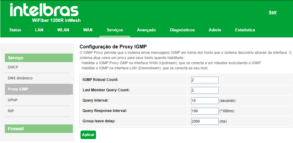
7.6.1.3. IGMP Proxy Configuration
IGMP Proxy allows the system to send IGMP messages on behalf of hosts that the system has discovered through the interface. The system acts as a proxy for its hosts when enabled.
7.6.1.4. UPnP Configuration
On this page you can configure the UPnP(Universal Plug and Play) function.
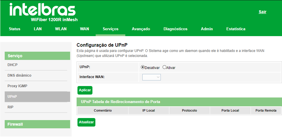
» UPnP: select Disable or Enable the UPnP function.
» Interface WAN: selects the WAN interface to enable the UPnP function.
7.6.1.5. RIP Configuration
On this page you can configure the use of dynamic routing using the RIP protocol.
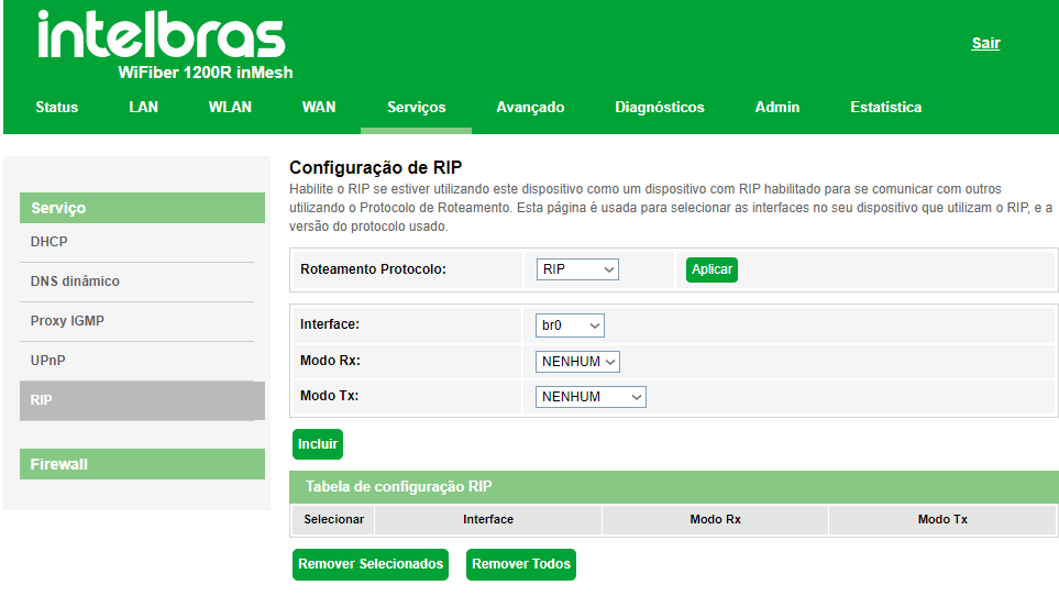
» RIP: select Disable or Enable the RIP function.
» Interface: select the interface on which the function will operate.
» RX Mode: select the version of the RIP protocol allowed for receiving..
» TX Mode: select the RIP protocol version used in the transmission.
» RIP Configuration table: displays the RIP function's configuration table.
7.6.2. Firewall
Through this menu you can set up port forwarding rules.
7.6.2.1. ALG
This page is used to Enable or Disable the ALG services.
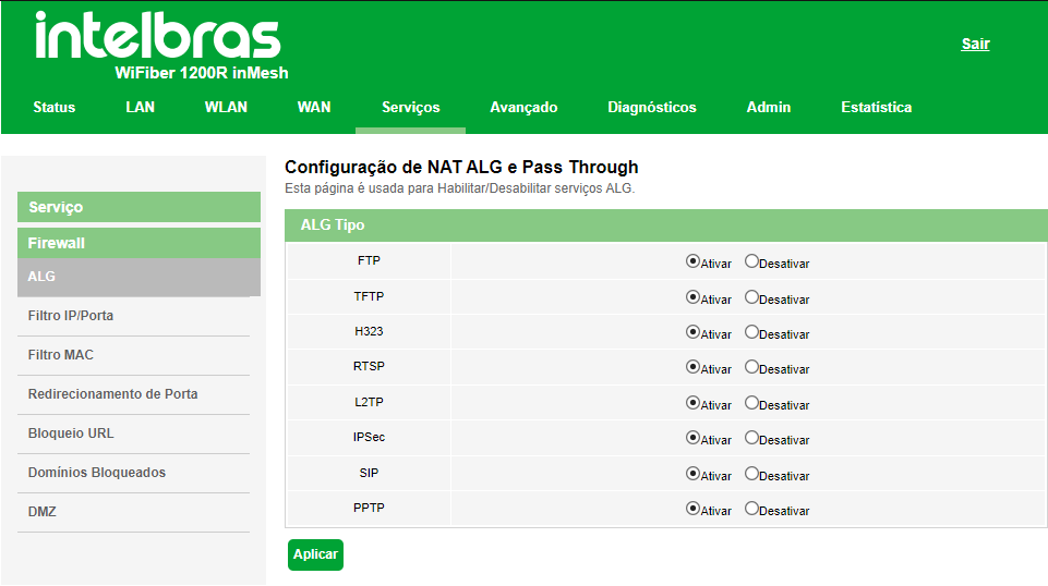
» ALG type: Enable or Desable te desired ALG service types.
7.6.2.2. IP/Port Filter
On this page it is possible to restrict the local network from accessing certain IPs and ports.
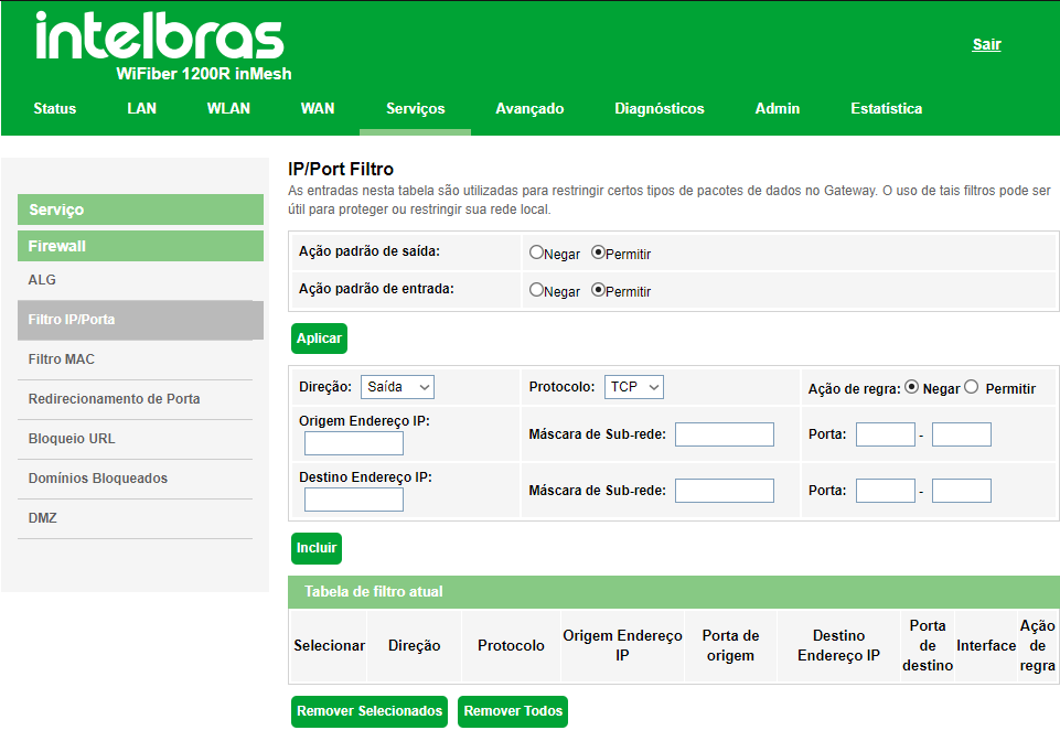
» Standard output action: select the default behavior of the IP Filter/Port function in the uplink direction.
» Standard input action: select the default behavior of the IP Filter/Port function in the downlink direction.
• Deny: only deny the added rules.
• Allow: Allow only the added rules.
» Protocol: select the protocol used by the rule.
» Rule Action: select the rule's action.
• Deny: deny the configured rule.
• Allow: allow the configured rule.
» Source IP address: enter the source IP that will be applied to the rule.
» Subnet Mask: enter the netmask of the source IP hat will be applied to the rule.
» Port: enter the start and end source port that will be applied to the rule. In the case of a single port, repeat the samevalue in the fields.
» Destination IP address: enter the destination IP that will be applied to the rule.
» Subnet mask: enter the netmask of the destination IP that will be applied to the rule.
» Port: enter the start and end destination port that will be applied to the rule. In the case of a single port, repeat thesame value in the fields.
» Current filter table: lists all the configured rules.
7.6.2.3. MAC Filter
On this page it is possible to restrict MAC addresses from the local network from accessing the Internet.
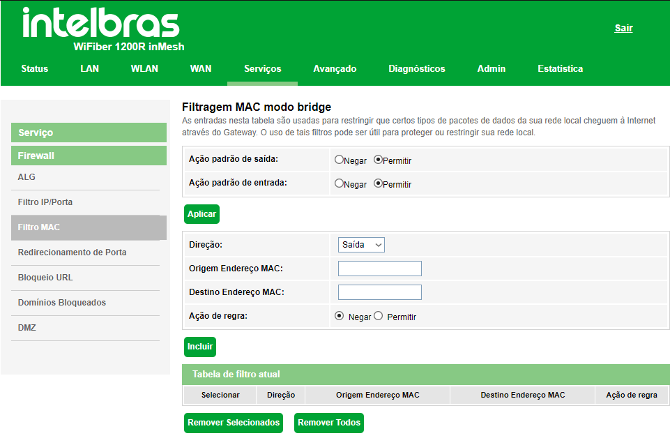
» Standard output action: select the default behavior of the MAC Filter function in the uplink direction.
» Standard input action: select the default behavior of the MAC Filter function in the downlink direction.
» Direction: select whether the MAC address will be barred from communicating in the downlink or uplink direction.
» Source MAC Address: enter the desired source MAC address and click Add.
» Destination MAC address: enter the desired destination MAC address and click Add.
7.6.2.4. Port forwarding
On this page it is possible to redirect services to a specific device behind NAT.
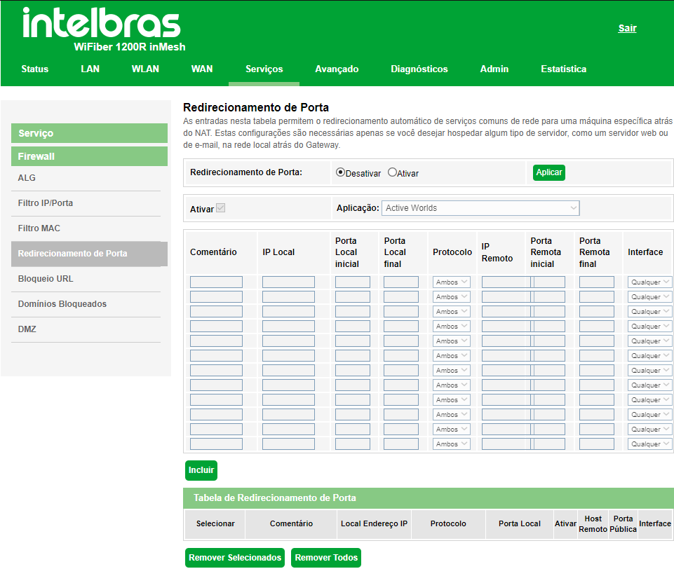
» Port forwarding: select Disable or Enable the rules and press the Apply button.
» Enable: select Enable use a list with several applications with their own already prepared redirection rules, search for the desired application and by selecting it the redirection rules will complete themselves. If yourapplication is not in the list, you must manually fill in.
» Comment: enter a comment for the rule.
» Local IP: enter the IP address of the device on your internal network that will receive the redirected traffic.
» Initial Local Port: Enter the port or range of ports to which Internet traffic will be directed on the device indicated inthe IP Address field. To enter a single port, repeat the same value in the fields (start - end).
» Final Local Port:: enter the port or range of ports visible through the Internet. Traffic received on these ports will beredirected to the local ports. To enter only a single port, repeat the same value in the fields (start - end).
» Protocol: select the transport protocol to be used.
• Both: the rule will apply for both TCP and UDP.
• TCP: the rule will apply only to the TCP protocol.
• UDP: the rule will apply only to the UDP protocol.
» Initial Remote Port: enter the initial port to which you will concentrate the Internet traffic that will be directed to thedevice port indicated in the local port.
» Final Remote Port: enter the final port to which you will concentrate the internet traffic that will be directed to the porton the device indicated in the local port field. To enter a single port, repeat the same value from the initial field.
» Interface: select the WAN interface to which the rule will be applied.
» Port forwarding table: displays the table with all the configured rules.
Note.: The maximum limit is 32 port forwarding rules (shared between UPNP and manual rules)7.6.2.5. URL Blocking
On this page it is possible to restrict access to certain web pages. The blocking is done through keywords present in the URLs.
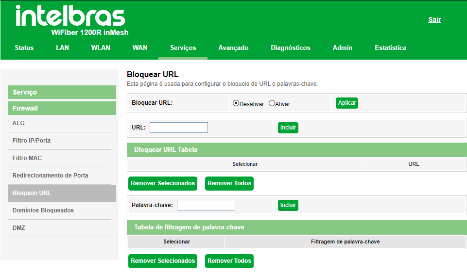
» URL Blocking: select Disable or Enable the function, and press the Apply button.
» URL: enter the URL that you want to use in the filter.
» Keyword: enter the word you want to use in the rule's URL filter.
7.6.2.6. Blocked Domains
On this page it is possible to restrict access to certain web domains.
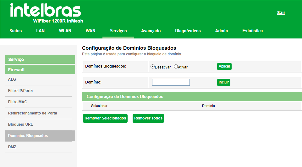
» Blocked domains: Select Disable or Enable the function and press the Apply button.
» Domain: Enter the internet domain you want to use in the filter.
7.6.2.7. DMZ
On this page you can set up a single device in the DMZ. The device set up in the DMZ will receive all traffic directed from the Internet to the local network.
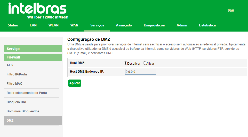
» DMZ Host: select Disable or Enable the DMZ Function and press the Apply Button.
» Host DMZ IP: enter the IP address of the device configured in the DMZ.
7.8. Advanced
On this page advanced settings are performed.
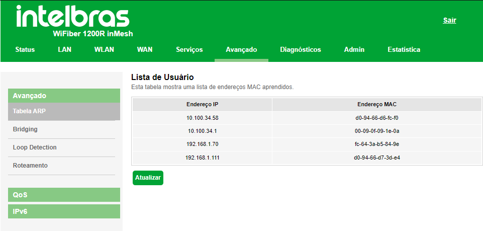
7.8.1.1. ARP Table
This table shows a list of MAC addresses learned from the source IP.
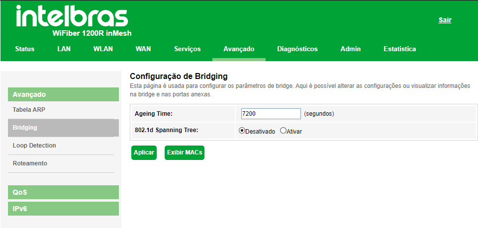
7.8.1.2. Bridging
On this page you can view the bridge settings and the attached ports.
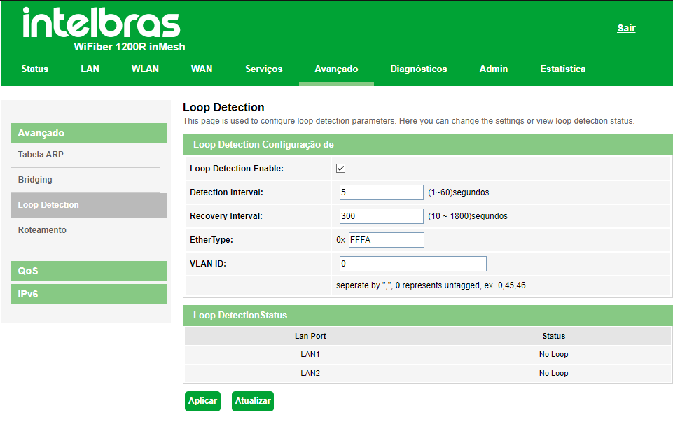
7.8.1.3. Loop Detection
On this page you can change the loop detection parameters in the ONT and also view its status.
7.8.1.4. Routing Configuration
Through this menu you can set up access routes to the desired networks.
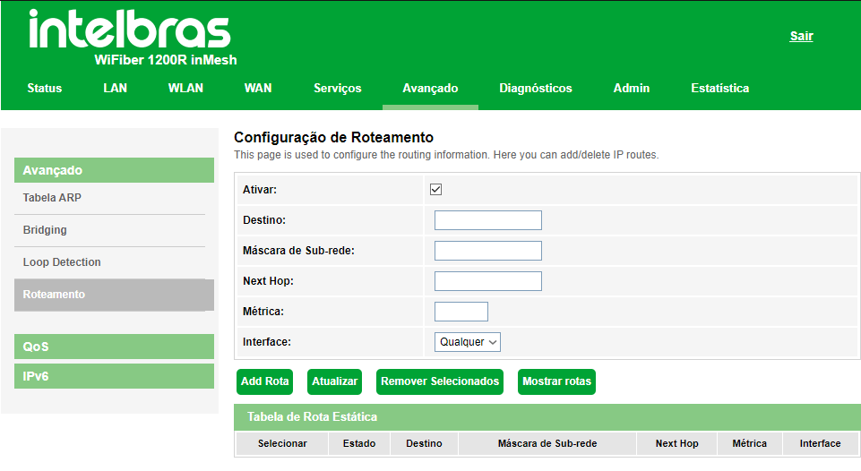
» Enable: select the option for entering a static route.
» Destination: enter the desired destination network.
» Subnet Mask: Enter the netmask of the destination address.
» Next Hop: enter the IP address of the destination network access gateway. If you leave this information blank, you will need to enter which WAN interface will be used.
» Metric: Enter the metric used by the route.
» Interface: Select the desired WAN interface or select Any.
» Static Route Table: displays the configured static routes.
Note: a maximum of 8 (eight) static IPv4 routes are allowed.

7.8.2. QoS Settings
Through this menu you can configure the QoS (Quality of Service) function to provide quality of service for various requirements and applications used in the network, optimizing and distributing bandwidth.
7.8.2.1. QoS Policy
On this page you can enable and configure the QoS function of the optical modem.

» QoS: if enabled, the optical modem will prioritize the traffic according to the settings made.
» QoS queue configuration: select the type of the scaling method:
• PRIO: In this mode (Strict Priority), the highest priority queue will take up all the bandwidth. Packets in the lowestpriority queue will only be forwarded after all packets in the highest priority queue have been forwarded.
• WRR: In this mode (Weight Round Robin) the packets from all the queues will be sent according to the weight ofeach queue, this weight indicates the proportion occupied by the resource.
» Queue: The optical modem has 4 priority queues, Q1 being the highest priority and Q4 being the lowest priority:
• Enable: if enabled, the optical modem will enable the priority queue.
• Weight: available only in WRR mode, and indicates the weight of the row.
» QoS Bandwidth Config: if enabled, you can configure the bandwidth limit of the WAN interface.
7.8.2.2. QoS Classification
On this page you can view QoS classification rules.
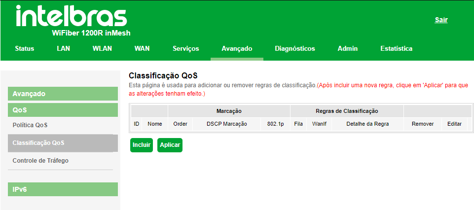
To add new rules, click Add:

» Rule Name: enter a name for the rule
» Rule Order: enter the priority of the rule.
» Assign IP Precedence/DSCP/802.1p: select how the optical modem will assign the QoS information in the packet::
• Precedence: the packet will be assigned to the configured queue.
• DSCP: DSCP value added to the Ethernet packet.
• 802.1p: 802.1p value added to the Ethernet packet.
» QoS rule type: select how the optical modem will identify the packet to perform QoS classification:QoS:
• Port: QoS assignments will be applied to any packet received on the specified port.
• EtherType: QoS assignments will only be applied to incoming packets that have the specified ethertype
• IP Protocol: the QoS assignments will be applied only to the received packets, according to the various configuration parameters. When you do not fill in any of the fields, it is understood as any value.
• MAC address: QoS assignments will only be applied to incoming packets that have the specified MAC address (source and/or destination).
Note: the rule will only be applied after it is added and the Apply button is pressed.7.8.2.3. Traffic Control
On this page it is possible to configure via ip address which device will have priority in the bandwidth allocation.
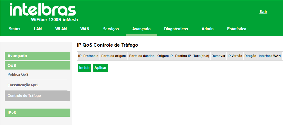
To add new rules, click Add:
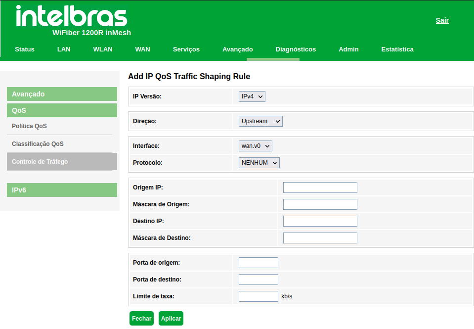
» » IP Version: select the desired option: IPv4 or IPv6.
» Direction: select whether the rule is for Upstream or Downstream.
» Interface: select the interface that should follow the rule
» Source IP: enter the source IP address used by the rule.
» Source Mask: enter the source mask used by the rule
» Destination IP: enter the destination IP address used by the rule.
» Destination Mask: enter the destination mask used by the rule.
» Destination port: enter the destination port used by the rule.
» Source port: enter the source port used by the rule.
» Rate limit: enter the rate limit in kb/s used by the rule.
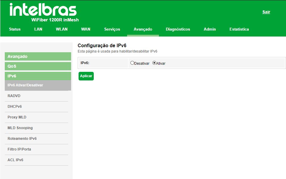
7.8.3. IPv6 Settings
7.8.3.1. Enable/Disable IPv6
This page is used to Enable/Disable IPv6.
7.8.3.2. RADVD settings
On this page you can configure the parameters used by the RADVD service..
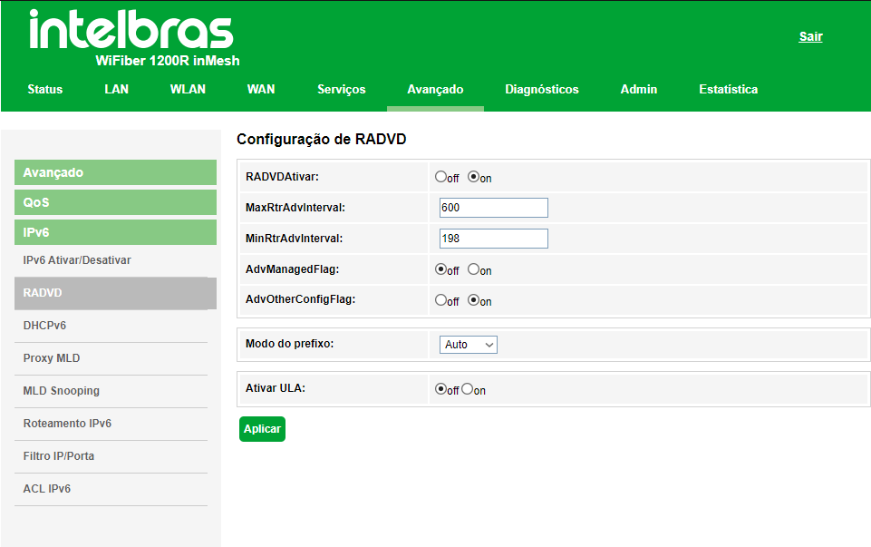
» RADVD Enable: Defines whether the Router Advertisement Daemon (RADVD) stays enabled or not.
» MaxRtrAdvInterval: maximum time for RA messages to be sent when the optical modem receives no RS(Router Solicitation).
» MinRtrAdvInterval: minimum time for RA messages to be sent when the optical modem receives no RS(Router Solicitation).
» AdvManagedFlag (M) / AdvOtherConfigFlag (O): The M and O flags define the method by which clients will learn IPv6 addresses from the DHCPv6 server:
• Flag M (AdvManagedFlag): when enabled, tells the device attached to its LAN interface that the IPv6 address will be assigned via the DHCPv6 server.
• Flag O (AdvOtherConfigFlag): when enabled, tells the connected device on its LAN interface how to use the DHCPv6 server to receive other settings (DNS, for example).
Note: the default option (M=off, O=on) is used when configuring the IPv6 addresses of clients connected to the optical modem's LAN when the prefix delegation option is enabled in the WAN settings.
» Modo de prefijo:
• Auto: this mode is used in conjunction with the prefix delegation option. This option causes the optical modem to send RA messages on your LAN according to information received from your WAN's DHCPv6 server.
• Manual: this mode is used to configure the parameters and information contained in RA messages transmitted on the optical modem's LAN.
Note: use this option only if required by your access provider7.8.3.3. DHCPv6 Settings
On this page you can configure how the DHCPv6 server works.
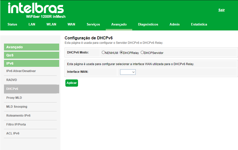
» Modo DHCPv6: select the DHCPv6 server operating mode:
• None: disables the DHCPv6 server.
• DHCP Relay: enter the IP address of the DHCP server to which the optical modem will forward messages
• DHCP Server enables you to enter DHCPv6 server settings manually. Use this method only if required by your provider.
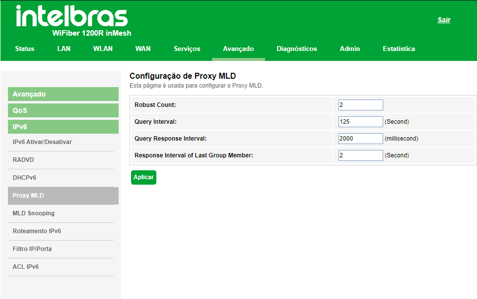
7.8.3.4. MLD Proxy Settings
On this page you configure the MLD Proxy Services.
7.8.3.5. Configurações MLD Snooping
On this page you can configure to enable MLD Snooping services.
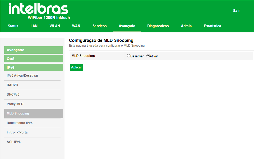
» MLD Snooping: When you select Enable, the LAN interface will start snooping MLD messages.
7.8.3.6. Static IPv6 routing configuration
NOn this page you configure the static IPv6 routes used by the optical modem.
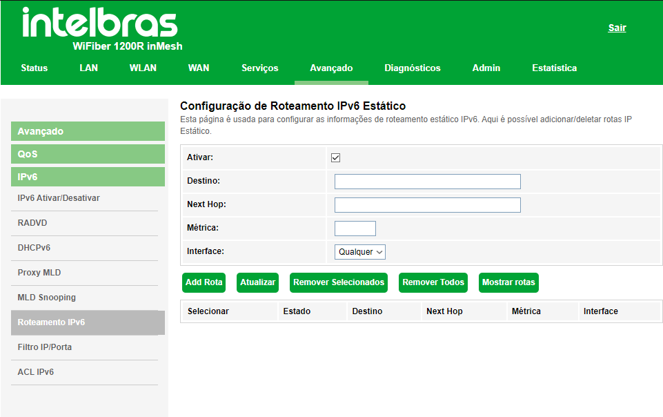
» » Enable: select Enable to allow adding static IPv6 route.
» Destination: enter the destination IPv6 network and also the network prefix size.
» Next Hop: enter the IPv6 address of the next hop (range) of the desired destination network.
» » Metric: enter the value of the metric used by the route.
» Interface: select a interface utilizada para alcançar a rede de destino desejada.
» Static IPv6 route table: displays the table with the manually configured IPv6 routes.
7.8.3.7. IP Filter/IPv6 Port
On this page it is possible to restrict the local network from accessing certain IPs and ports
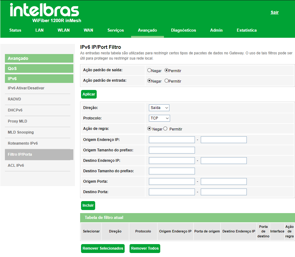
» » Default outbound action: select the default action for the rules entered (Deny or Allow) on outbound packets.
» select the default action for the entered rules (Deny or Allow) upon package entrance.
» Direction: select whether the rule is for Incoming or Outgoing.
» Protocol: select the protocol used by the rule.
» Source IP address: enter the source IPv6 address used by the rule.
» Source prefix size: enter the prefix size of the source IPv6 address used by the rule
» Destination IP address: enter the prefix size of the destination IPv6 address used by the rule.
» Destination prefix size: enter the prefix size of the destination IPv6 address used by the rule.
» Source port: enter the source port or range of ports used by the rule.
Note: to insert a single port, repeat the same value in the fields.
» Port Destination: enter the destination port or range of ports used by the rule.
Mote: to insert a single port, repeat the same value in the fields.
» Current filter table: displays the IPv6 filter rules already applied to the device.
7.8.3.8. IPv6 ACL
This page is used to allow/deny access to services running on the optical modem.
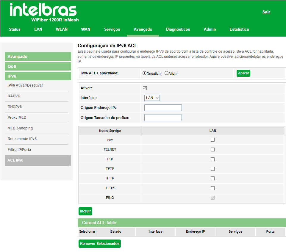
» IPv6 ACL capacity: select Enable or Disable the ACL function and press the Apply button..
» Interface: select to enable the LAN or WAN interface.
» Service Name: select which services are enabled by the optical modem and press the Add button.
» IPv6 ACL Table: lists all the configured rules
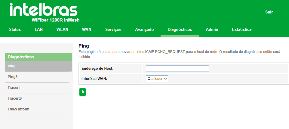
7.9. Diagnóstics
The Diagnostics menu allows you to perform basic connectivity diagnostics of the optical modem using features such as ping (IPv4/IPv6) and Traceroute (IPv4 and IPv6) in its submenus
7.10. Admin
Through this menu it is possible to make maintenance settings for the optical modem, such as changing the access password and performing backups.
7.10.1. GPON Settings
This page is used to configure the parameters for your GPON network access.
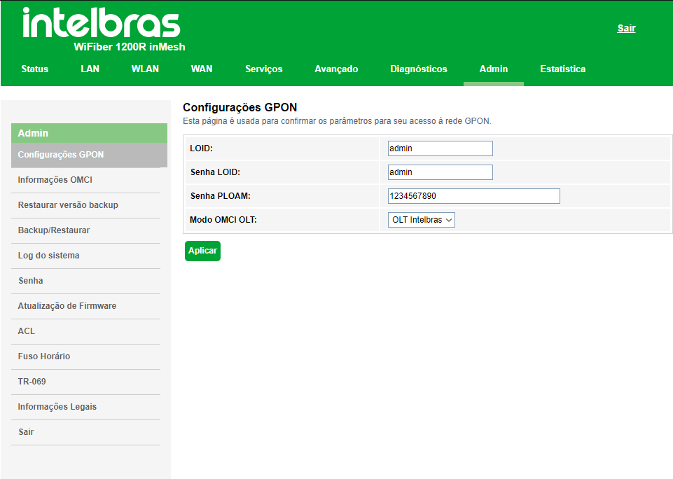
» OMCI OLT mode: Select the mode for sending OMCI status information according to the OLT used.
Note: When selecting the Huawei OLT, the WiFiber 1200R will reboot so that the settings are applied to this
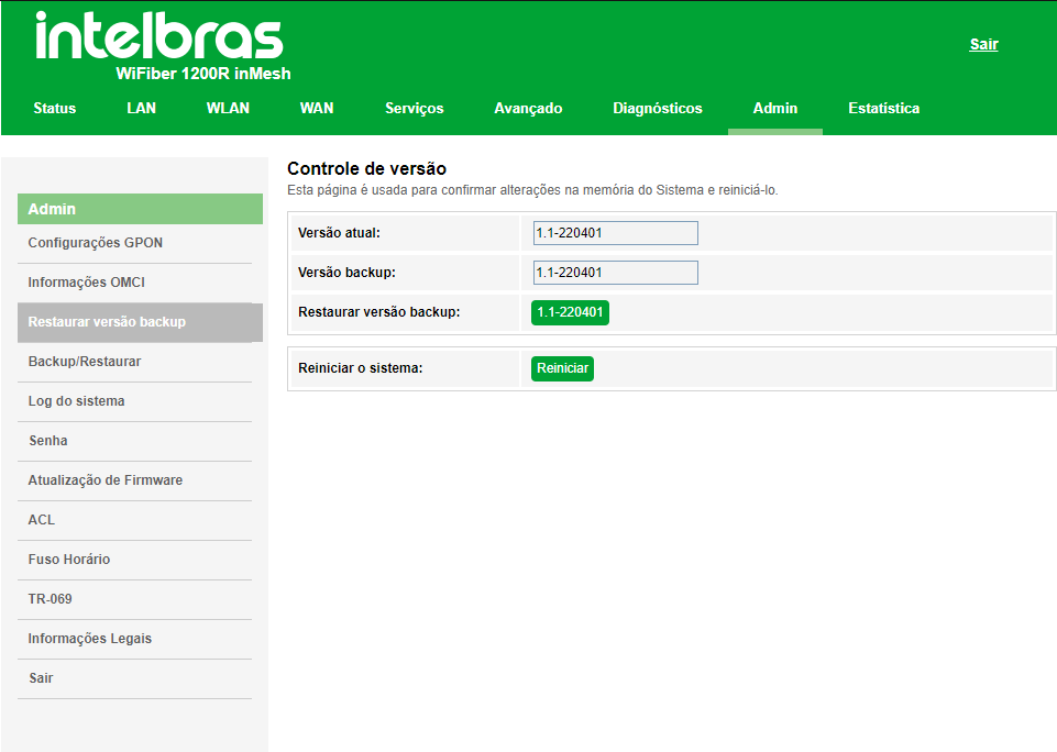
7.10.2. Restore backup version
7.10.3. Backup/Restore
On this page you can save and restore the optical modem's settings, as well as reset it to the factory default
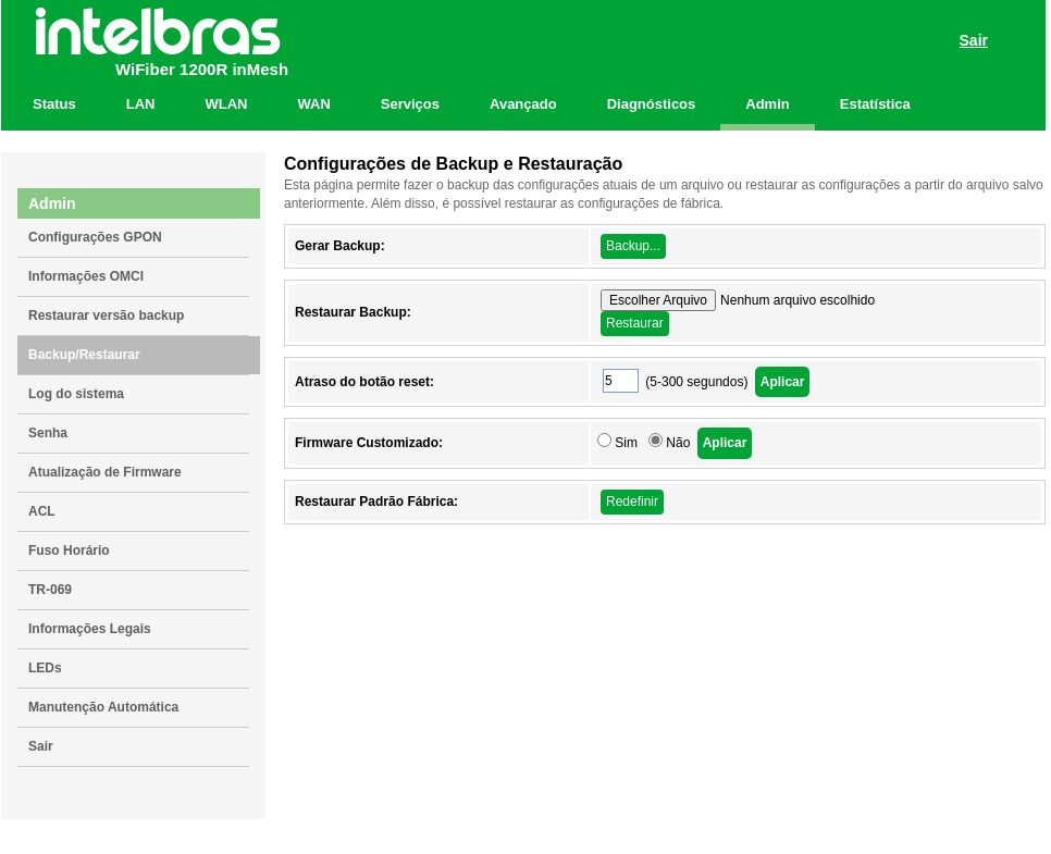
» Generate backup: click the Backup button to save the settings on your computer.
» Restore backup: to restore a configuration previously, select the backup file and click the Restore button.
» Reset button delay: click the Apply button to define how long the physical reset button must be held down for the settings to be restored to the factory default.
» Custom Firmware: Click Yes and Apply to change the current configuration to the product's default configuration so that it remains configured even after a factory reset. (Reboot required)
» Restore factory default: click the Reset button to reset the optical modem to the factory default.
Note: the factory default restore process does not change the following fields: GPON Vendor ID, LOID, LOID Password, and PLOAM Password.
7.10.4. System Log
Here you can observe the events that occur in the system.
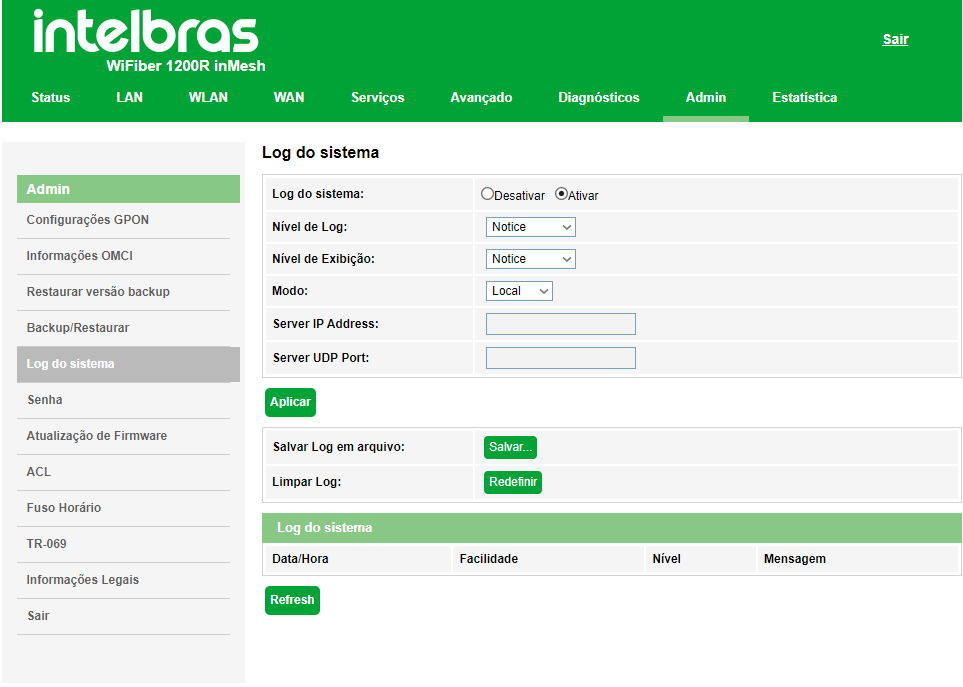
» System Log:
• Enable: you will receive the logs generated by the system.
• Disable: you stop receiving the logs generated by the system.
» Log level: defines which log types will be captured.
» Display level: allows you to filter which log types should appear
» Mode: concerns where you want to receive the logs.
7.10.5. Password Setup
On this page you can change the password to access the GPON/EPON optical modem for the Admin and User users.
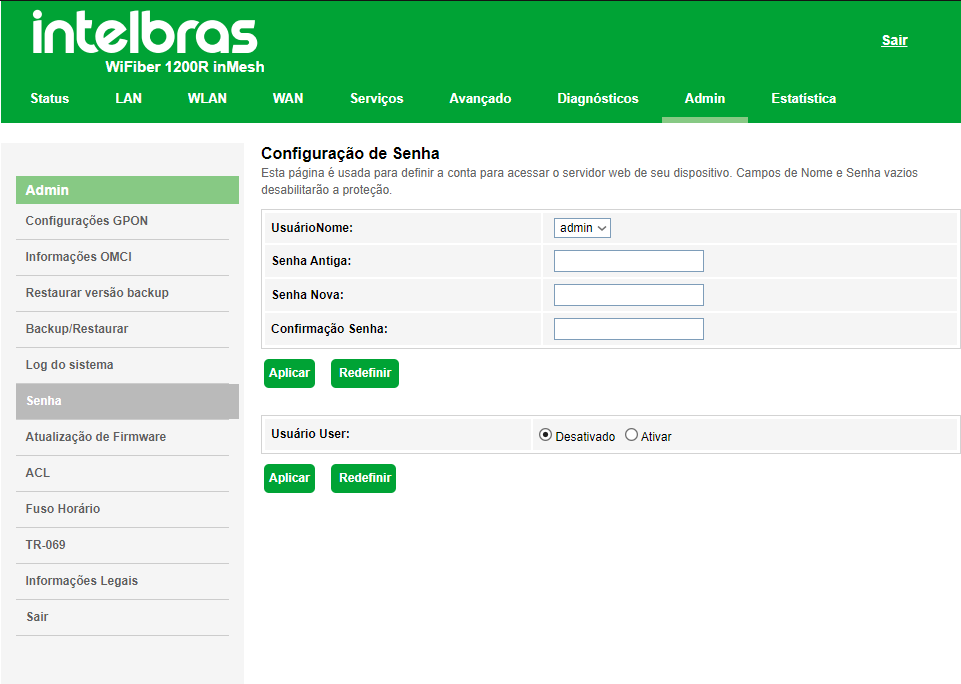
» User: select the username you want to change the password for.
» Old Password: enter the old password that will be replaced.
» New Password: enter the new password.
» Password Confirmation: confirm the new password.
7.10.6. Firmware update
On this page you can perform a firmware update for the optical modem.
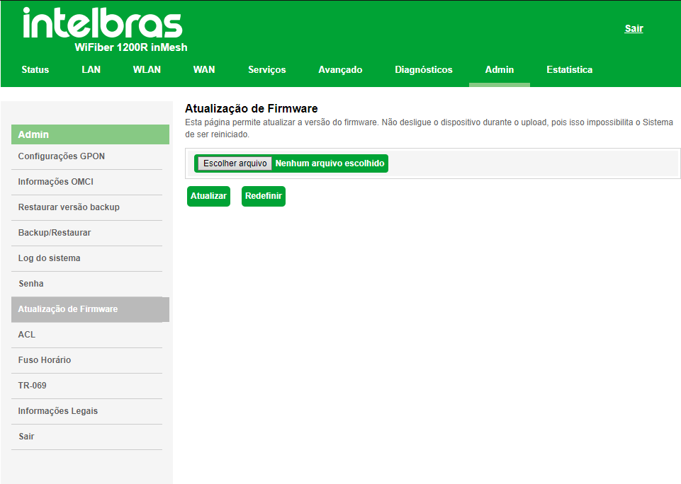
» Update: select the desired firmware and click Update to update the optical modem.
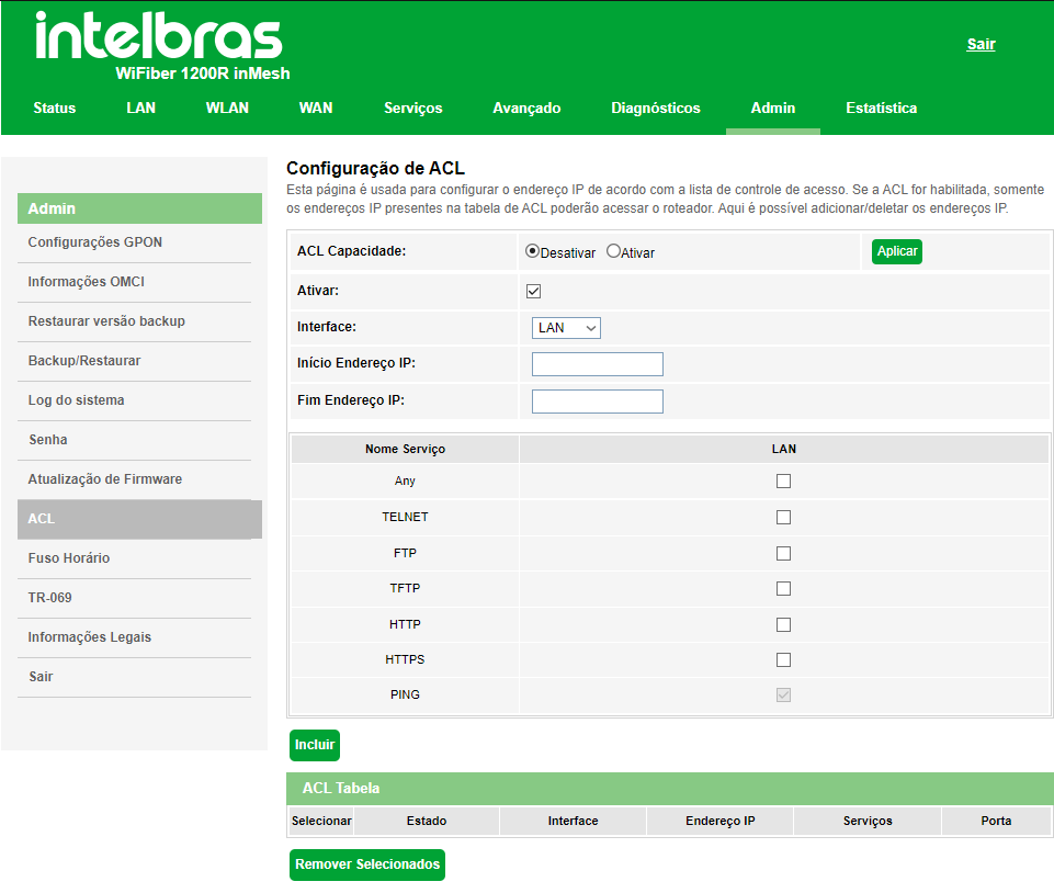
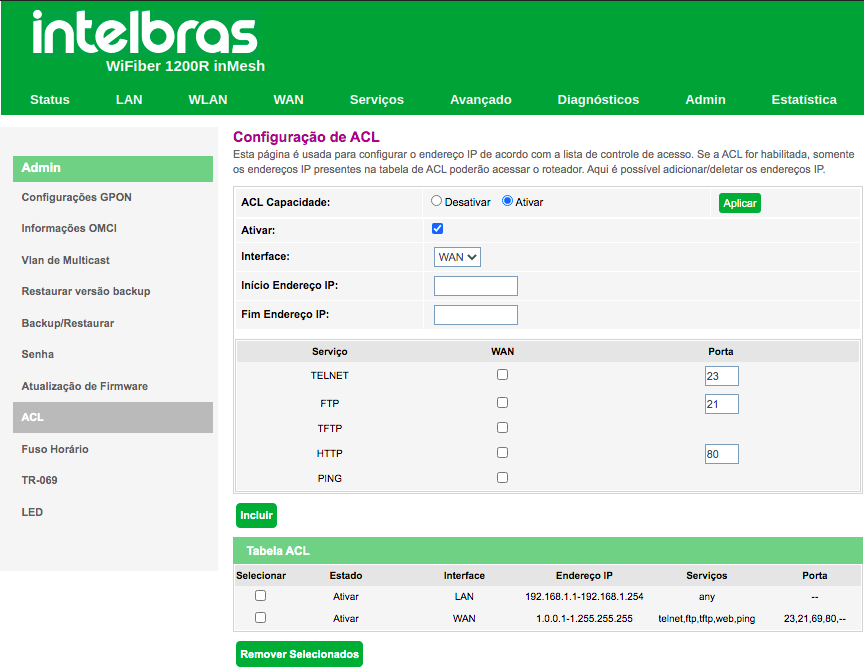
7.10.7. ACL Configuration
This page is used to configure the IP address according to the access control list. If ACL is enabled, only the IP addresses present in the ACL table will be able to access the optical modem on the given services and ports. Here you can add/delete the IP addresses.
7.10.8. Time Zone configuration
On this page you can configure the synchronization of the system date and time using a public time server over the Internet.
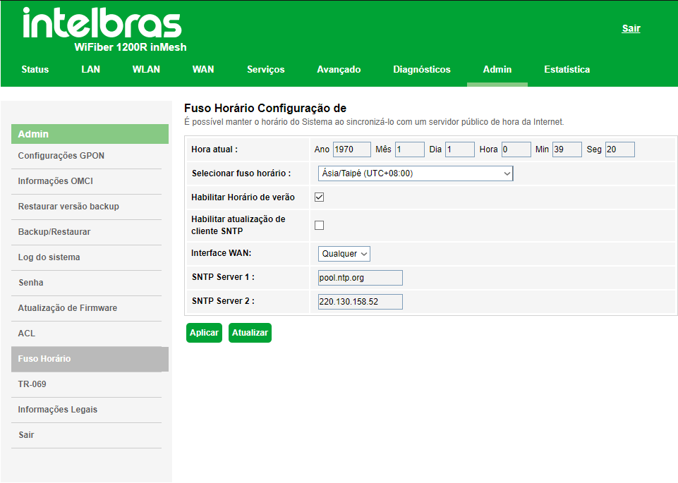
» Current time: in this field you can check the date and time currently used by the system. It is also possible to make the configuration manually, just enter the desired information and press the Apply button.
Note: information entered manually will be lost in case of a reboot of the optical modem.
» Select time zone: select the desired time zone
» Enable summer time: enables the use of daylight saving time.
» Enable SNTP client update: enables the use of SNT client updatingP.
» Interface WAN: select the WAN interface used to establish communication with the Internet Time Server.
» SNTP server: enter the IP address of the desired time server.
7.10.9. TR-069 Configuration
This page is used to configure the TR-069 CPE. Here you can change ACS parameter settings.
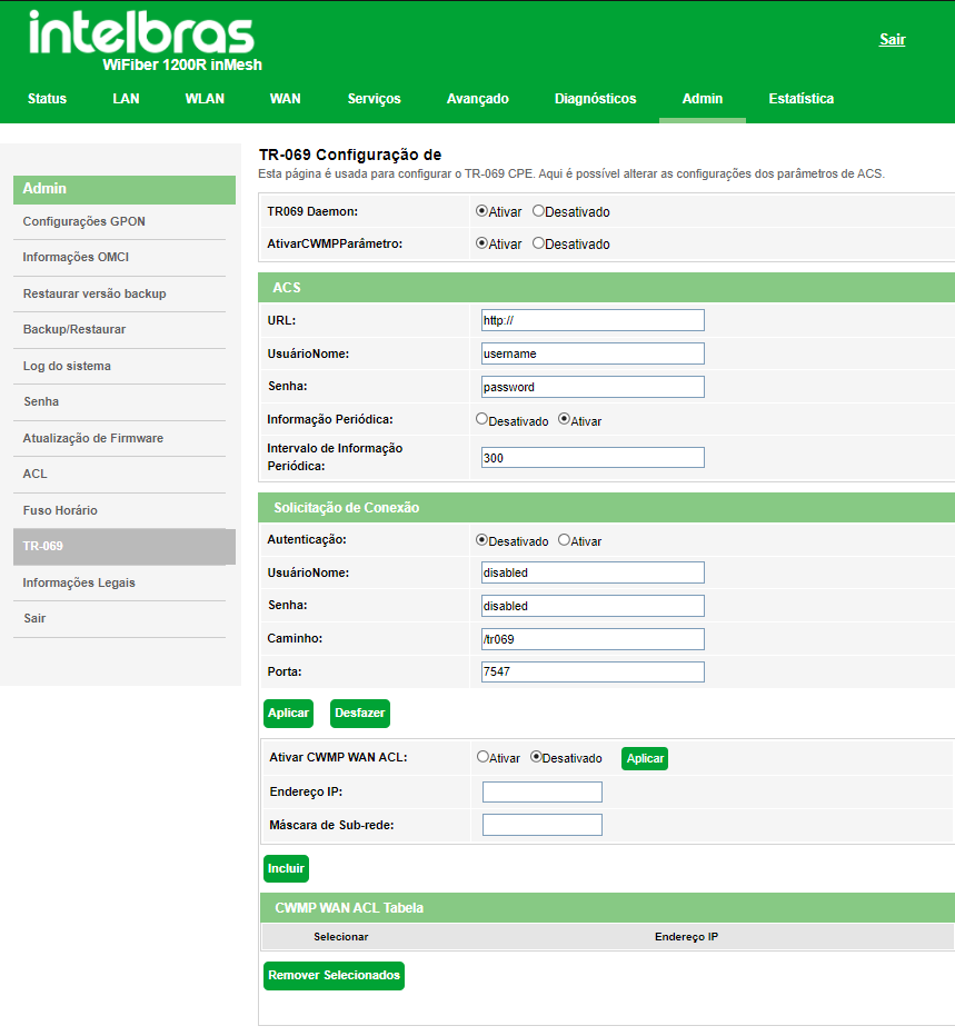
Enable/Disable Services
» TR069 Daemon:Enable/Disable service.
» CWMP Parameter: Enable/Disable service.
ACS Server
On this tab you fill in the ACS information where the product will periodically report its status to the configured server.
» URL: enter the ACS destination URL.
» User: enter the ACS user.
» Password: enter the ACS password
OBS: the password allows only these symbols: @ . : / - _
» Periodic Information: Enable/Disable periodic reporting according to the desired time in the field below.
» Periodic Information Interval: enter the time in second(s) when the equipment will send the status to the ACS server.
Connection Request
In this tab you enter a User and Password for the TR069 server to manage the equipment.
» Authentication: Enable or disable authentication by ACS user.
» User: enter a user of your preference.
» Password: enter a password of your preference.
OBS: the password allows only these symbols: @ . : / - _
CWMP WAN ACL Access
If CWMP WAN ACL is enabled, only the IP addresses present in the ACL table will be able to access the optical modem.
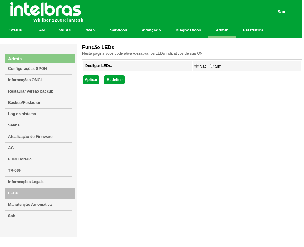
7.10.10. Enable/Disable LED
In this page you can Enable/Disable the LEDs for WiFiber 1200R
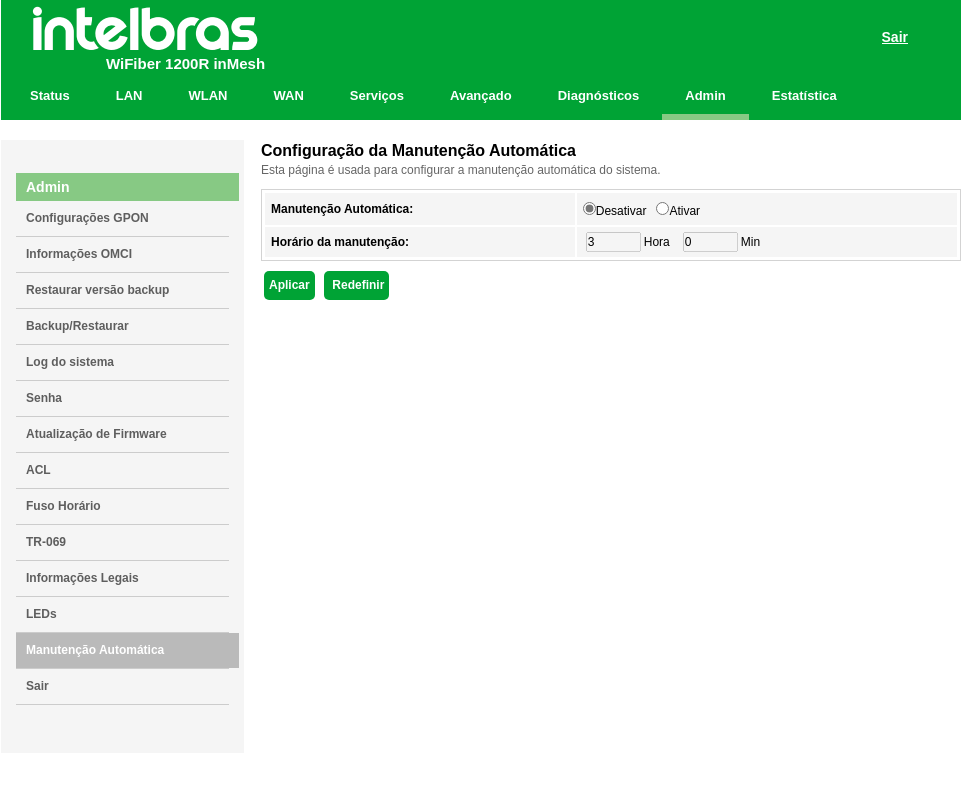
7.10.11. Auto Maintenance
In this page you can Enable/Disable automatic maintenance so the system will reboot automatically every day in the scheduled time*
* Ensure that NTP is enabled and configured for your timezone.
7.10.12. Legal Information
On this page you can read again the terms of use that were accepted.
7.10.13. Log out
On this page you can logout of the ONT and close your session.
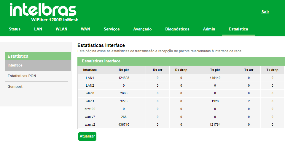
7.11. Statistics
Using this menu you can view statistics of received and transmitted packets per interface (LAN, WAN and PON).
8. Warranty Terms
It is hereby expressly stated that this contractual warranty is conferred under the following conditions:
Name of client:
Client signature:
Invoice No.:
Date of purchase:
Model:
Serial No.:
Retailer:
It is hereby expressly stated that this contractual warranty is conferred under the following conditions:
1. All parts, pieces and components of the product are warranted against any manufacturing defects, which they may eventually present, for a period of one (1) year, being this period of three (3) months of legal warranty plus nine (9) months of contractual warranty, counted from the date of purchase of the product by the Consumer, as stated in the invoice of the product, which is an integral part of this Term throughout the national territory. This contractual warranty includes the exchange of parts, pieces and components that present manufacturing defects. If no manufacturing defect is found, but defect(s) arising from improper use, the Consumer will bear these expenses.
2. The product installation should be done according to the Product Manual and/or Installation Guide. If your product requires installation and configuration by a qualified technician, please contact a qualified and specialized technician, considering that the costs for these services are not included in the product's price.
3. Once the defect is confirmed, the Consumer must immediately contact the nearest Authorized Service listed by the manufacturer - only these are authorized to examine and remedy the defect during the warranty period foreseen herein. If this is not done, this warranty will be void, since it will be characterized as a violation of the product.
4. In the event that the Consumer requests home assistance, he/she must go to the nearest Authorized Service in order to check the fee for the technical visit. If it is necessary to collect the product, the resulting expenses, such as transportation and security costs to and from the product, will be the responsibility of the Consumer.
5. The warranty will totally lose its validity in the occurrence of any of the following hypotheses: a) if the defect is not defective in manufacturing, but caused by the Consumer or by third parties strange to the manufacturer;b) if the damages to the product come from accidents, claims, nature agents (lightning, floods, landslides, etc.), humidity, electric network voltage (overvoltage caused by accidents or excessive fluctuations in the network), installation/use in disagreement with the user's manual or resulting from the natural wear of the parts, pieces and components; c) if the product has suffered chemical, electromagnetic, electrical or animal influences (insects, etc.); d) if the product's serial number has been tampered with or erased; e) if the device has been tampered with.
6. This warranty does not cover loss of data, therefore, it is recommended, if applicable to the product, that the Consumer make a regular backup copy of the data on the product
7. Intelbras is not responsible for the installation of this product, nor for any attempts of fraud and/or sabotage on its products. Keep the software updates and applications used up-to-date, if applicable, as well as the network protections required for protection against intrusions (hackers). The equipment is guaranteed against vices within its normal conditions of use, and it is important to be aware that, because it is an electronic equipment, it is not free of frauds and cheats that may interfere with its correct operation.
8. After its useful lifespan, the product must be delivered to an Intelbras authorized service center or directly disposed of inan environmentally appropriate manner, avoiding environmental and health impacts. If you prefer, the battery as well asother Intelbras electronics without use, can be discarded at any Green Eletron collection point (manager of electro electronicwaste with which we are associated). If you have any questions about the reverse logistics process, please contact us byphone (48) 2106-0006 or 0800 704 2767 (Monday to Friday from 8am to 8pm and on Saturdays from 8am to 6pm) or bye-mail suporte@intelbras.com.br.
As these are the conditions of this supplemental warranty term, Intelbras S/A reserves the right to change the general, technical, and aesthetic features of its products without prior notice.
All images in this manual are illustrative.

Customer Support: (48) 2106 0006
Fórum: forum.intelbras.com.br
Support via chat: intelbras.com.br/suporte-tecnico
Support via e-mail:: suporte@intelbras.com.br
Customer service::: 0800 7042767
Where to buy? Who installs?: 0800 7245115
Produced by: Intelbras S/A – Indústria de Telecomunicação Eletrônica Brasileira
Rodovia SC 281, km 4,5 – Sertão do Maruim – São José/SC - 88122-001
Origin China 05.22