
Compatibilização
WiFiber 1200R
InMesh Setup Guide
This page teaches you how to enable and configure WiFiber with the InMesh function of the product and how to add the routers of the Wi-Force intelbras line as your secondary nodes.
This procedure is for WiFiber configuration in controller mode, if you want to use a Wi-Force router as a controller, access the complete guide by clicking here.
All information on this page is authored by Intelbras and its institutions.
1. Specifications
Products that support the InMesh function.
| Specifications | Value |
|---|---|
| WiFiber Line (Controller) | WiFiber 121 AC |
| WiFiber 120 AC | |
| WiFiber 1200R | Wi-Force Line (Agent) | W5-1200F |
| W5-1200G | |
| GF-1200 | Maximum number of secondary nodes | 6 | Recommended signal level between nodes | down to -65dBm |
2. Configuring the controller
Before configuring your WiFiber 1200R as an InMesh network controller, you need to update the firmware version available on the website by clicking here. Then configure it by following the steps below:
» In the WLAN menu, configure the 5GHz and 2.4GHz network with the same SSID and password, using WPA2 encryption and set a static channel for 5GHz frequency only;
» After setting up the Wi-Fi network, go to WLAN > InMesh > InMesh Configuration, check the option Controller and then click the button Apply, according to the following image:
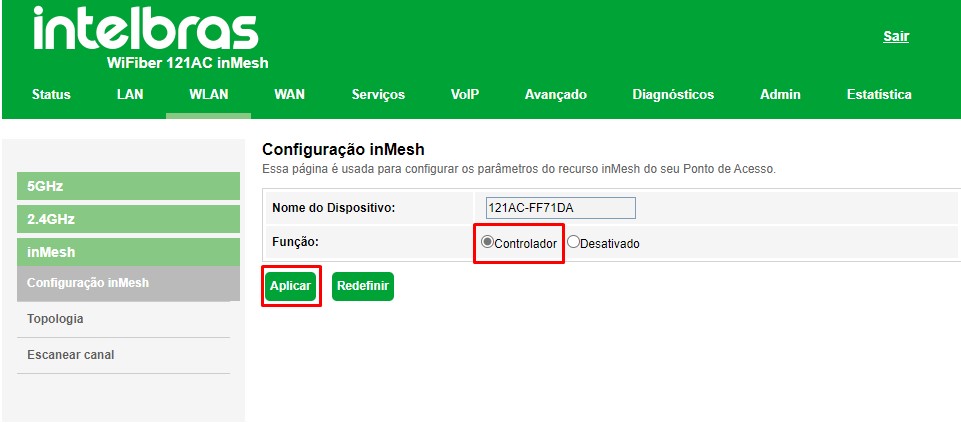
After following the procedure above, your WiFiber will be configured as the main node of the InMesh network.
3. Adding Secondary Node to InMesh Network
To add a new router to your WiFiber's InMesh network, it must be from the Intelbras Wi-Force line, as specified in item 1, and also be updated with the firmware available on the website, by clicking here. After updating the router, restore it to factory default.
3.1. Adding via web interface
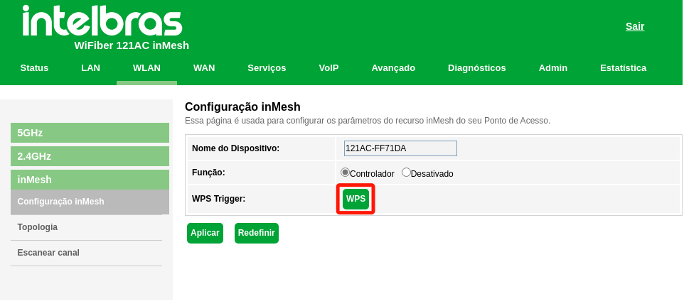
» Access WiFiber WEB interface and enter WLAN > InMesh > InMesh Configuration menu;
» In the WPS Trigger function, click on WPS, which is on the side (As shown below). After that, notice that the WiFiber WPS LED will start blinking;
» With the router updated and in the factory default, turn it on near your WiFiber;
» The router polls for 2 minutes until some controller asks to connect;
» As soon as the WPS stops blinking, the pairing between WiFiber and router is completed;
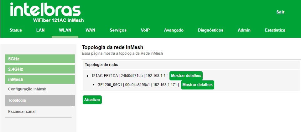
» In the WLAN > InMesh > Topology menu, you can view the newly added router.
After completing the addition, follow the steps in item 4 to know how to position your node and get a better performance from your network.
3.2. Adding via WPS button
» With the router updated and in the factory default, turn it on near your WiFiber;
» Press WiFiber's WPS button, the LED should start flashing;
» When pairing is complete, WiFiber's WPS will be static;
• Note.: This procedure can take up to 2 minutes.
» To check if the router has been added, access the WLAN > InMesh > Topology menu;;
3.3. Adding via cable
» Turn on the secondary router (factory default) to power and wait a few seconds;
» Connect a network cable between the LAN port of WiFiber and the LAN port of the secondary router and wait;
• Note.: This procedure can take up to 2 minutes.
» To check if the router has been added, access the WLAN > InMesh > Topology menu;;
4. InMesh Network Management
Consider having already configured your mesh network according to theitem 2 e item 3.
4.1. Signal level between nodes
For good performance from your InMesh network, consider positioning your node with a signal level down to -65 dBm.
To check the signal level we have two options, via the main node (controller) or through the secondary node (agent).
Note.: your InMesh network will still work if your node has a signal below –65dBm, but not at its best capacity.4.1.1. Checking head node signal
» Go to WLAN > InMesh > Topology menu;
» Click on the Show Details option of the first device in the topology;
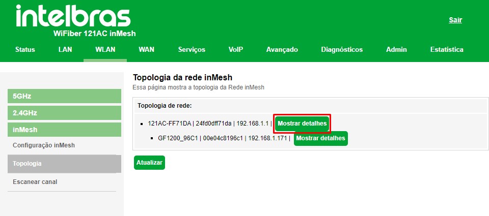
» Ao clicar, aparecerá a seguinte janela com as seguintes informações:
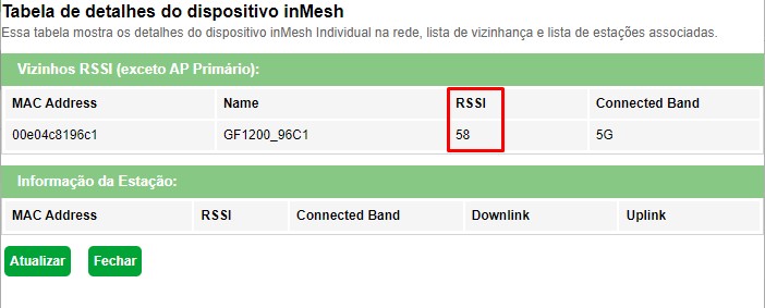
• MAC Address: MAC address of the connected node
• Name: secondary node name
• RSSI: signal level that the primary node is receiving from the secondary. To transform into dBm, subtract the value by 100. Ex from the image below: 58 – 100 = -42dBm
• Connected Band: band frequency that the secondary node is connected to;
With this information, you can check whether or not you should reposition your secondary node for a better experience.
4.1.2 Checking secondary node signal
» Access the WLAN > InMesh > Topology menu of the head node;
» Check the IP address of the secondary node, as shown in the image below;
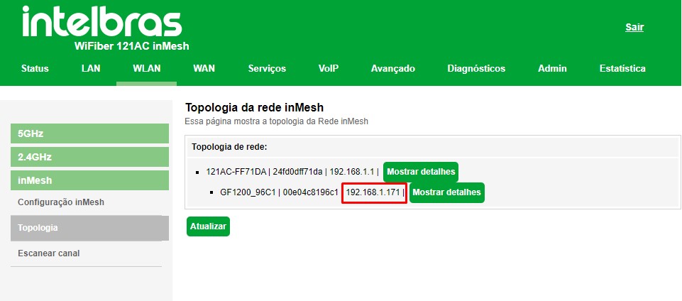
» Access the IP address and proceed with the installation wizard to configure an interface access password;
» After finishing the wizard, access the secondary node dashboard;
» On the dashboard, in the table Connection Status in the column Connection (MESH) you can see the signal level that the secondary node is receiving from the node it is connected to;
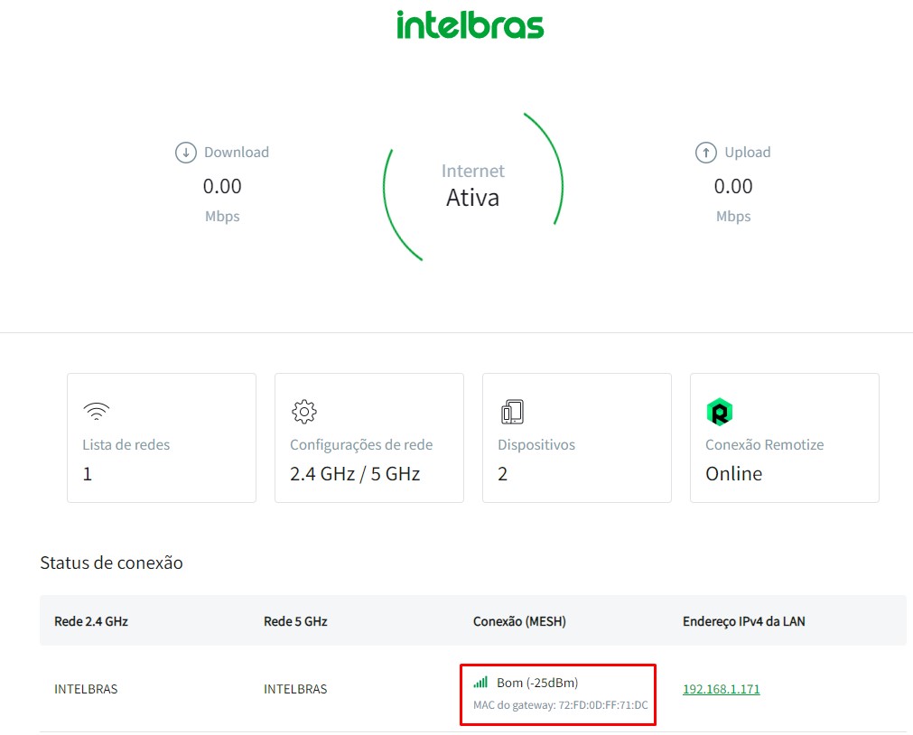
With this information, you can check whether or not you should reposition your secondary node for a better experience.

Customer Support: (48) 2106 0006
Fórum: forum.intelbras.com.br
Support via chat: intelbras.com.br/suporte-tecnico
Support via e-mail:: suporte@intelbras.com.br
Customer service::: 0800 7042767
Where to buy? Who installs?: 0800 7245115
Produced by: Intelbras S/A – Indústria de Telecomunicação Eletrônica Brasileira
Rodovia SC 281, km 4,5 – Sertão do Maruim – São José/SC - 88122-001
Origin China 05.22